
1. Informações de segurança
Please read and understand all safety information and operating instructions before using this multimeter. Failure to follow these instructions may result in electric shock, fire, or damage to the meter.
- Sempre verifique se os cabos de teste estão conectados corretamente e se a chave seletora de função está ajustada para a faixa correta antes de realizar qualquer medição.
- Não tente medir voltages or currents exceeding the maximum rated values for this meter.
- Tenha extrema cautela ao trabalhar com circuitos energizados. Tensão elevadatagpode ser perigoso.
- Never open the meter casing unless specifically instructed for battery or fuse replacement. Ensure test leads are disconnected before opening.
- Substitua a bateria quando o indicador de bateria fraca acender para garantir leituras precisas.
- Não utilize o multímetro se ele parecer danificado ou se o isolamento dos cabos de teste estiver comprometido.
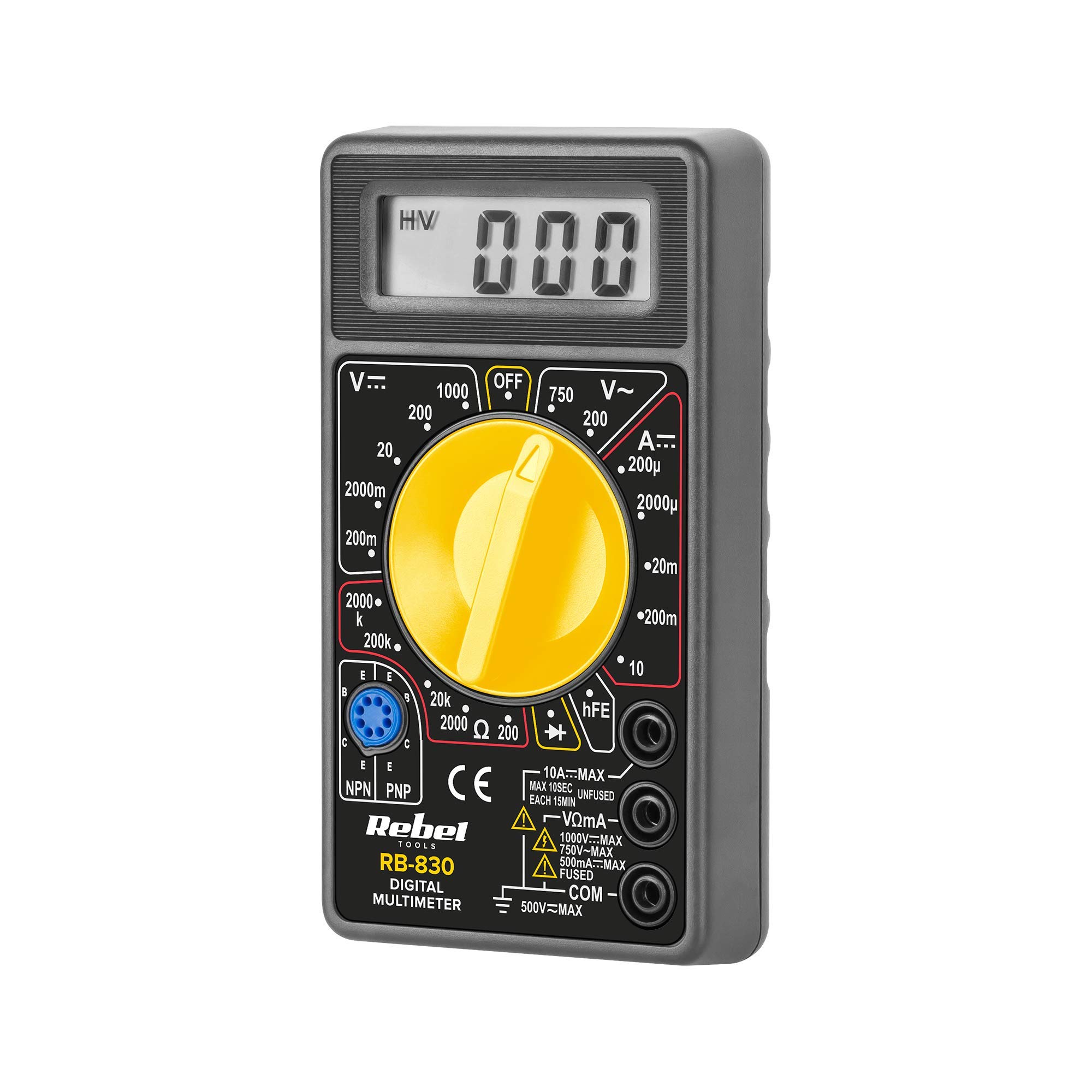
Figura 1: Traseira view of the Rebel MIE-RB-830 Multimeter, showing the battery compartment cover and a warning label. The label advises removing test leads before opening the case to avoid electrical shock and to install fuses with correct amp/volt ratings. It also indicates the power supply is a 9V battery, type NEDA 1604 9V 6F22.
2. Produto acabadoview
The Rebel MIE-RB-830 is a compact, battery-operated digital multimeter designed for measuring DC/AC voltage, DC current, resistance, diode, and transistor (hFE) values. It is suitable for general electrical testing and troubleshooting.
2.1. Componentes
- Multímetro digital
- Cabos de teste (vermelho e preto)
- 9V Battery (may be included or sold separately)
- Manual do usuário (este documento)

Figura 2: The Rebel MIE-RB-830 Digital Multimeter shown with its accompanying red and black test leads. The multimeter features a large LCD display and a rotary function switch.

Figura 3: Fechar-se view of the red and black test leads. These leads are essential for connecting the multimeter to the circuit under test.
3. Configuração
3.1. Instalação da bateria
- Certifique-se de que o multímetro esteja desligado e que todos os cabos de teste estejam desconectados.
- Locate the battery compartment cover on the back of the meter (refer to Figure 1).
- Desaperte o(s) parafuso(s) de fixação e remova cuidadosamente a tampa.
- Insert a new 9V battery (NEDA 1604 or 6F22 type), observing the correct polarity (+ and -).
- Recoloque a tampa do compartimento da bateria e fixe-a com o(s) parafuso(s).
3.2. Conectando cabos de teste
- Conecte o vermelho test lead to the "VΩmA" input jack.
- Conecte o preto test lead to the "COM" (common) input jack.
- For current measurements exceeding 200mA (up to 10A), connect the red test lead to the "10A" input jack.
4. Instruções de operação
4.1. Seleção de Função
Turn the rotary switch to the desired measurement function and range. Always start with a higher range if the approximate value is unknown to prevent overloading the meter.
4.2. Medição da tensão CCtage (V–)
- Ajuste a chave rotativa para o volume CC desejado.tage (V–) range (e.g., 20V, 200V).
- Conecte o fio de teste vermelho ao lado positivo (+) do circuito e o fio de teste preto ao lado negativo (-).
- Leia o vol.tage valor no display LCD.
4.3. Medição do Vol ACtage (V∼)
- Ajuste a chave rotativa para a tensão CA desejada.tage (V∼) range (e.g., 200V, 750V).
- Conecte os cabos de teste ao circuito CA.tage fonte.
- Leia o vol.tage valor no display LCD.
4.4. Measuring DC Current (A–)
Cuidado: To measure current, the meter must be connected in series with the circuit. Never connect the meter in parallel with a voltage source when in current mode, as this can damage the meter and the circuit.
- Ajuste a chave rotativa para a faixa de corrente contínua (A–) desejada (por exemplo, 20mA, 200mA, 10A).
- For currents up to 200mA, ensure the red lead is in the "VΩmA" jack. For currents up to 10A, move the red lead to the "10A" jack.
- Abra o circuito onde a corrente deve ser medida e conecte o medidor em série.
- Leia o valor atual no visor LCD.
4.5. Medição da resistência (Ω)
Cuidado: Certifique-se de que o circuito ou componente em teste esteja desenergizado antes de medir a resistência.
- Set the rotary switch to the desired Resistance (Ω) range (e.g., 200Ω, 2kΩ, 200kΩ).
- Conecte os cabos de teste ao componente ou circuito a ser medido.
- Leia o valor da resistência no visor LCD.
4.6. Teste de diodo (→|–)
- Set the rotary switch to the Diode Test (→|–) position.
- Connect the red test lead to the anode of the diode and the black test lead to the cathode.
- O visor mostrará o volume de avançotagqueda de tensão (tipicamente de 0.5V a 0.8V para diodos de silício).
- Inverta os terminais. O visor deve mostrar "OL" (Circuito Aberto) para indicar que o diodo está em bom estado.
4.7. Transistor (hFE) Test
- Coloque a chave rotativa na posição hFE.
- Identifique se o transistor é NPN ou PNP.
- Insert the transistor's emitter, base, and collector leads into the corresponding sockets on the hFE test socket.
- Leia o valor de hFE (ganho de corrente CC) no visor.
5. Manutenção
5.1. Substituição da bateria
When the low battery indicator appears on the display, replace the 9V battery as described in Section 3.1. Using a low battery can lead to inaccurate readings.
5.2. Substituição de fusíveis
If the current measurement function stops working, the fuse may need replacement. This operation should only be performed by qualified personnel.
- Certifique-se de que o multímetro esteja desligado e que todos os cabos de teste estejam desconectados.
- Open the back casing of the meter (this may involve more screws than just the battery compartment).
- Locate the blown fuse and replace it with a fuse of the exact same type and rating (e.g., F200mA/250V for mA range, F10A/250V for 10A range). Refer to the internal markings or specifications for precise fuse ratings.
- Carefully reassemble the meter, ensuring all screws are tightened.
5.3. Limpeza
Limpe o medidor com anúncios.amp cloth and mild detergent. Do not use abrasives or solvents. Keep the meter dry.
6. Solução De Problemas
| Problema | Possível causa | Solução |
|---|---|---|
| Sem imagem ou imagem fraca | Bateria fraca ou esgotada | Substitua a bateria de 9V. |
| Leituras incorretas | Low battery; Incorrect range selection; Poor test lead connection | Replace battery; Select appropriate range; Ensure leads are firmly connected. |
| A medição de corrente não está funcionando. | Blown fuse; Incorrect lead connection for current | Replace fuse (see Section 5.2); Ensure red lead is in "VΩmA" or "10A" jack as appropriate. |
| "OL" (Sobrecarga) exibido | Measured value exceeds selected range; Open circuit (for resistance/continuity) | Select a higher range; Check circuit for breaks. |
7. Especificações
| Função de Medição | Faixa | Precisão |
|---|---|---|
| Vol. DCtage (V–) | 200mV, 2V, 20V, 200V, 1000V | ±(0.5% + 2 dígitos) |
| Vol. CAtage (V∼) | 200 V, 750 V | ±(1.2% + 10 dígitos) |
| DC Current (A–) | 200µA, 2mA, 20mA, 200mA, 10A | ±(1.0% + 2 dígitos) |
| Resistência (Ω) | 200Ω, 2kΩ, 20kΩ, 200kΩ, 2MΩ | ±(0.8% + 2 dígitos) |
| Teste de diodo | Sim | Vol. Para frentetage queda |
| Teste de transistor (hFE) | Sim | hFE value |
| Fonte de energia | Bateria de 9V (NEDA 1604 ou 6F22) | |
| Mostrar | 3½ Digit LCD, Max. 1999 | |
| Dimensões | Aprox. 13.5 x 10 x 4 cm | |
| Peso | Approx. 107 grams (without battery) | |
| Temperatura de operação | 0°C a 40°C (32°F a 104°F) | |
| Temperatura de armazenamento | -10°C a 50°C (14°F a 122°F) | |
| Normas de segurança | CE, RoHS |
8. Garantia e Suporte
This Rebel MIE-RB-830 Digital Multimeter is covered by a standard manufacturer's warranty against defects in materials and workmanship. Please refer to the warranty card included with your purchase or contact your retailer for specific warranty terms and conditions.
For technical support or service inquiries, please contact the point of purchase or visit the official Rebel website para informações de contato.