1. Introdução
This manual provides essential information for the installation, operation, and maintenance of the SPABOY FX3U-24MT Programmable Logic Controller (PLC). The FX3U-24MT is an industrial control board featuring 14 digital inputs (DI), 10 digital outputs (DO), 6 analog inputs (AI), 2 analog outputs (AO), and communication interfaces including RS232 and RS485. It is designed for various industrial automation applications.
2. Informações de segurança
Siga sempre as seguintes diretrizes de segurança para evitar ferimentos e danos ao equipamento:
- Certifique-se de que a energia esteja desligada antes de realizar qualquer fiação ou manutenção.
- Somente pessoal qualificado deve instalar, operar e realizar a manutenção deste dispositivo.
- Verifique se todas as conexões da fiação estão corretas e seguras antes de ligar a energia.
- Do not expose the PLC to excessive moisture, dust, or extreme temperatures.
- Utilize equipamento de proteção individual (EPI) adequado ao trabalhar com sistemas elétricos.
3. Produto acabadoview
The SPABOY FX3U-24MT PLC is a compact and versatile industrial control unit. It integrates various I/O capabilities and communication options for flexible system design.
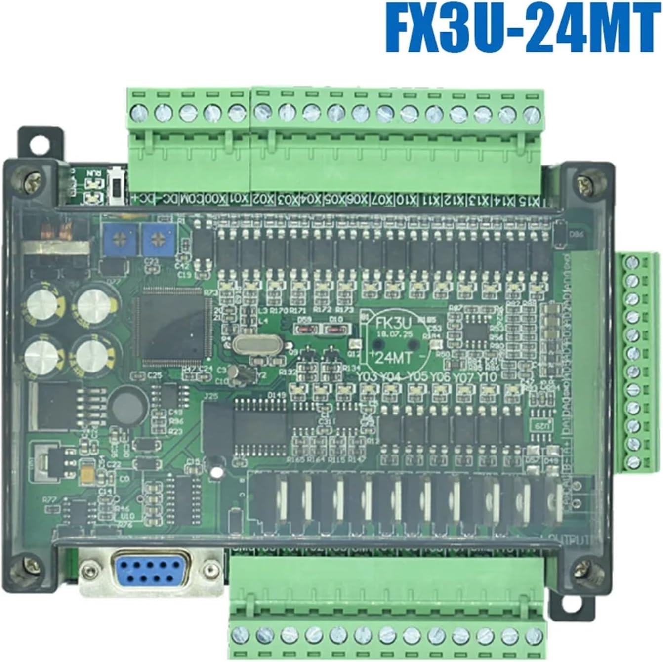
Figure 1: SPABOY FX3U-24MT PLC. This image displays the top view of the PLC, highlighting the main circuit board, input/output terminals, and communication ports.
3.1. Principais características
- Digital Inputs (DI): 14 pontos
- Digital Outputs (DO): 10 points (Transistor type)
- Analog Inputs (AI): 6 canais
- Analog Outputs (AO): 2 canais
- Comunicação: RS232, RS485 ports
- Fonte de energia: Typically 24V DC (refer to specifications for exact voltage gama)
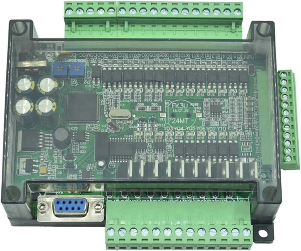
Figure 2: SPABOY FX3U-24MT PLC with terminal blocks. This image provides an angled view, emphasizing the green terminal blocks for wiring connections.
4. Configuração
4.1. Montagem
The PLC is designed for panel mounting. Secure the unit using screws through the designated mounting holes on the enclosure. Ensure adequate ventilation around the unit to prevent overheating.
4.2. Fiação
All wiring should be performed with the power supply disconnected. Refer to the terminal labels on the PLC for correct connections.
- Fonte de energia: Connect the 24V DC power supply to the designated power terminals (e.g., 24V, GND). Observe polarity.
- Entradas digitais (X0-X13): Connect input devices (e.g., sensors, switches) to the digital input terminals. Ensure common ground connections are correctly established.
- Saídas digitais (Y0-Y9): Connect output devices (e.g., relays, indicators) to the digital output terminals. The FX3U-24MT uses transistor outputs, requiring careful consideration of load current and external power if driving inductive loads.
- Analog Inputs (AD0-AD5): Connect analog sensors (e.g., temperature, pressure transducers) to these terminals. Ensure proper shielding for analog signals to minimize noise.
- Analog Outputs (DA0-DA1): Connect analog actuators or control devices to these terminals.
- Communication Ports (RS232/RS485): Connect communication cables to the respective ports for programming or data exchange with other devices.
4.3. Instalação de software
To program the FX3U-24MT PLC, compatible programming software is required. Typically, software like GX Works2 or GX Developer is used. Install the software on your PC and ensure the correct drivers for the communication interface (e.g., USB-to-RS232 converter) are installed.
5. Instruções de operação
5.1. Programação
Create your control logic using the PLC programming software. Common programming languages include Ladder Diagram (LD). Upload the compiled program to the PLC via the RS232 port.
5.2. Digital I/O Operation
Digital inputs respond to ON/OFF signals. Digital outputs provide ON/OFF control to connected devices. Monitor and control these states within your PLC program.
5.3. Analog I/O Operation
Analog inputs convert varying voltage or current signals into digital values that can be processed by the PLC. Analog outputs convert digital values from the PLC into varying voltage or current signals to control analog devices. Calibration may be required for accurate analog readings and outputs.
5.4. Comunicação
The RS232 port is primarily used for programming and debugging. The RS485 port supports multi-drop communication, allowing the PLC to communicate with other devices (e.g., HMIs, other PLCs, VFDs) using protocols like Modbus RTU.
6. Manutenção
- Inspeção regular: Verifique periodicamente se todas as conexões da fiação estão bem apertadas e se há sinais de corrosão.
- Limpeza: Keep the PLC enclosure clean and free from dust and debris. Use a soft, dry cloth. Do not use solvents or abrasive cleaners.
- Controle ambiental: Assegurar que o ambiente operacional permaneça dentro das faixas de temperatura e umidade especificadas.
- Programas de backup: Regularly back up your PLC programs to prevent data loss.
7. Solução De Problemas
7.1. Power Indicator Not On
- Check the 24V DC power supply connection and ensure it is providing the correct voltage.
- Verify power supply polarity.
7.2. PLC Not Communicating with PC
- Ensure the correct communication cable (e.g., RS232) is used and properly connected.
- Verify the COM port settings in the programming software match the PC's port settings.
- Check for proper driver installation for any USB-to-serial converters.
7.3. Digital Input/Output Malfunction
- Check wiring to the input/output device.
- Verify the status of the input/output in the PLC programming software's monitoring mode.
- Ensure the external power supply for output devices is correctly connected and functional.
7.4. Analog Input/Output Inaccuracy
- Check sensor wiring and calibration.
- Ensure proper shielding for analog signal cables to reduce electrical noise.
- Verify scaling parameters in the PLC program for analog values.
8. Especificações
| Recurso | Especificação |
|---|---|
| Modelo | FX3U-24MT |
| Entradas Digitais (DI) | 14 pontos |
| Saídas Digitais (DO) | 10 points (Transistor) |
| Entradas Analógicas (AI) | 6 canais |
| Saídas Analógicas (AO) | 2 canais |
| Portas de comunicação | RS232, RS485 |
| Fonte de energia | 24V DC (typical) |
| Peso do item | 50 gramas (1.76 onças) |
| Dimensões da embalagem | 1.18 x 0.79 x 0.39 polegadas |
| Fabricante | SPABOY |
9. Garantia e Suporte
For warranty information and technical support, please refer to the documentation provided with your purchase or contact your vendor. Keep your purchase receipt for warranty claims.