1. Introdução
This manual provides essential information for the installation, operation, and maintenance of the SPABOY FX3U-14MT Programmable Logic Controller (PLC). The FX3U-14MT is an industrial control board featuring 14 digital inputs, 10 digital outputs, 6 analog inputs, 2 analog outputs, and RS232/RS485 communication interfaces. It is designed for various industrial automation applications.
Please read this manual thoroughly before using the product to ensure correct and safe operation.
2. Informações de segurança
Observe as seguintes precauções de segurança para evitar ferimentos pessoais e danos ao equipamento:
- Certifique-se de que a energia esteja desligada antes de realizar qualquer fiação ou manutenção.
- Somente pessoal qualificado deve instalar e realizar manutenção neste dispositivo.
- Não utilize o CLP em ambientes que excedam os limites especificados de temperatura, umidade ou vibração.
- Avoid exposing the device to direct sunlight, corrosive gases, or excessive dust.
- Proper grounding is essential for safe operation and to prevent electrical noise.
3. Produto acabadoview
The SPABOY FX3U-14MT PLC is a compact and versatile industrial control solution. Below is an image illustrating the main components and connection points.

Figura 3.1: Careca view of the FX3U-14MT PLC. This image shows the main circuit board, input/output terminal blocks, and the RS232 communication port.

Figura 3.2: Angulado view of the FX3U-14MT PLC, highlighting the side-mounted terminal blocks for various connections.
4. Configuração e instalação
4.1. Instalação Física
The PLC should be mounted in a stable, well-ventilated enclosure, away from sources of heat, vibration, and electromagnetic interference. Use appropriate mounting hardware to secure the board.
4.2. Conexão da fonte de alimentação
Connect a stable DC power supply (typically 24V DC, check specifications for exact voltage range) to the designated power terminals. Ensure correct polarity. Improper power connection can damage the device.
4.3. Wiring Digital Inputs (DI)
The FX3U-14MT features 14 digital inputs. Connect sensors, switches, and other input devices to the DI terminals. Refer to the wiring diagram for specific terminal assignments. Inputs are typically sink/source type, requiring careful consideration of external wiring.
4.4. Wiring Digital Outputs (DO)
The PLC provides 10 digital outputs. Connect actuators, relays, indicator lights, or other output devices to the DO terminals. Ensure the load current does not exceed the maximum rating per output. The FX3U-14MT variant uses transistor outputs.
4.5. Wiring Analog Inputs (AI)
The 6 analog inputs support standard industrial signals (e.g., 0-10V, 4-20mA). Connect analog sensors to these terminals. Proper shielding and grounding of analog signal cables are crucial to minimize noise interference.
4.6. Wiring Analog Outputs (AO)
The 2 analog outputs provide control signals for devices like variable frequency drives or proportional valves. Connect these devices to the AO terminals, ensuring compatibility with the output signal range.
4.7. Communication Ports (RS232/RS485)
Connect the PLC to a programming device or other communication equipment using the RS232 or RS485 ports. Use appropriate cables and ensure correct pin assignments for reliable data exchange.
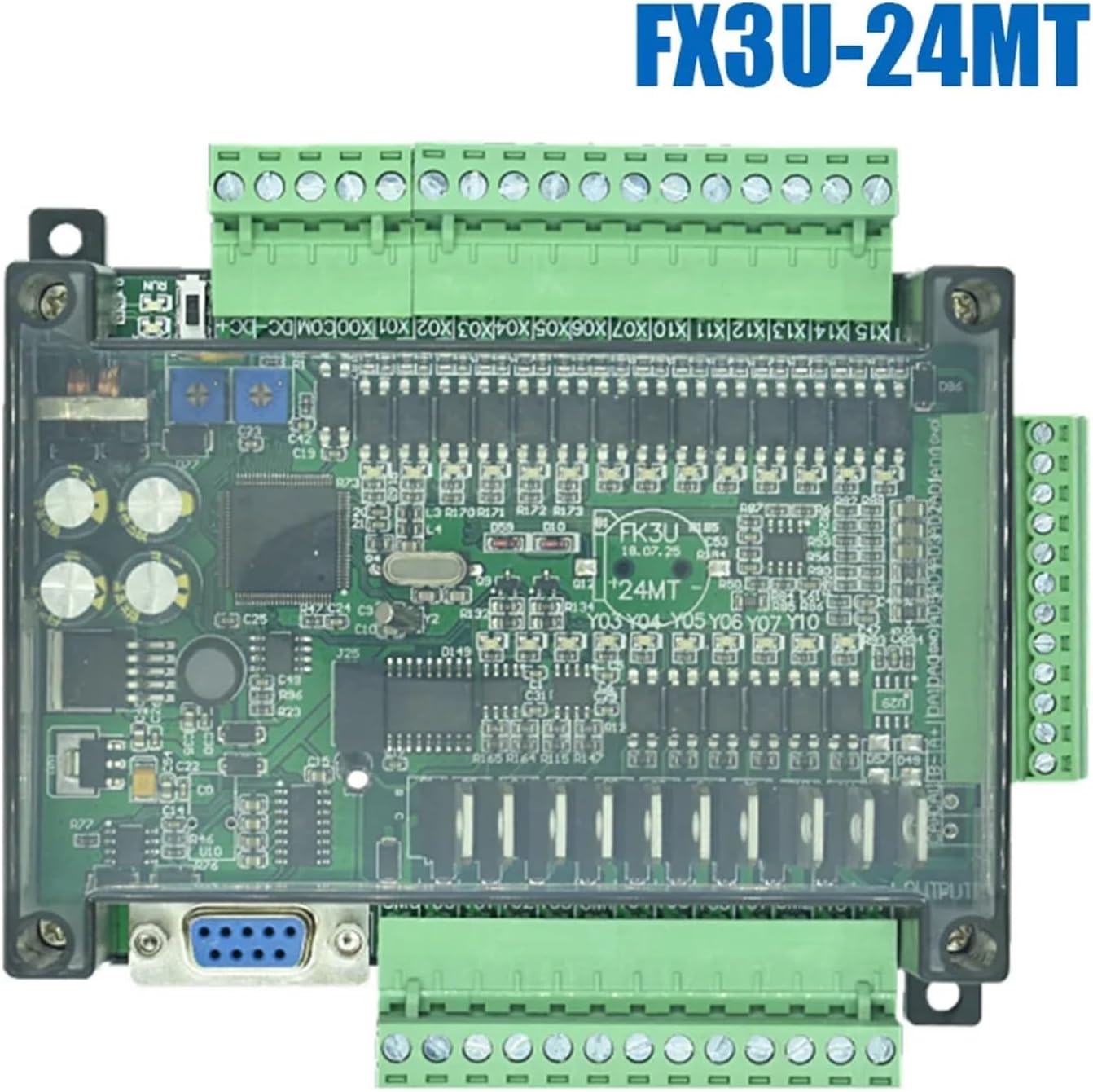
Figura 4.1: Lado view of the FX3U-14MT PLC, detailing the RS232 communication port and input/output wiring terminals.
5. Instruções de operação
5.1. Instalação e conexão de software
Install the appropriate PLC programming software (e.g., GX Works2/3 or compatible software) on your computer. Connect the computer to the PLC via the RS232 port using a suitable programming cable.
5.2. Programação do CLP
Develop your control logic using ladder diagram, instruction list, or other supported programming languages within the software. The FX3U series typically supports a rich instruction set for various control tasks.
5.3. Uploading and Downloading Programs
Once the program is complete, download it to the PLC's memory. Ensure the PLC is in STOP mode before downloading. After downloading, switch the PLC to RUN mode to execute the program. You can also upload existing programs from the PLC for backup or modification.
5.4. Monitoring and Debugging
Use the programming software to monitor the status of inputs, outputs, internal relays, and data registers in real-time. This feature is essential for debugging and verifying program logic.
6. Manutenção
A manutenção regular garante a longevidade e o funcionamento confiável do seu CLP.
- Limpeza: Periodically clean the PLC and its enclosure to prevent dust accumulation, which can lead to overheating or short circuits. Use a soft, dry cloth or compressed air.
- Verificações de conexão: Regularly inspect all wiring connections for tightness and signs of corrosion. Loose connections can cause intermittent operation or failures.
- Monitoramento Ambiental: Assegure-se de que o ambiente operacional permaneça dentro das faixas de temperatura e umidade especificadas.
- Programas de backup: Periodically back up your PLC programs to an external storage device to prevent data loss.
7. Solução De Problemas
This section provides solutions to common issues encountered during PLC operation.
| Problema | Possível causa | Solução |
|---|---|---|
| O PLC não liga. | Sem fonte de alimentação, volume incorretotage, reversed polarity, faulty power supply. | Check power connections, verify voltage and polarity, test power supply. |
| Os comandos não estão respondendo. | Incorrect wiring, faulty sensor, program logic error, input type mismatch. | Verify wiring, test sensor, check program logic, ensure input type (sink/source) matches. |
| Saídas não ativadas. | Incorrect wiring, faulty actuator, program logic error, overloaded output. | Verify wiring, test actuator, check program logic, ensure load is within output rating. |
| Communication errors. | Incorrect cable, wrong port settings (baud rate, data bits), driver issues. | Check cable integrity, verify communication settings in software and PLC, reinstall drivers. |
8. Especificações
Detailed technical specifications for the SPABOY FX3U-14MT PLC.
| Recurso | Especificação |
|---|---|
| Modelo | FX3U-14MT |
| Entradas Digitais (DI) | 14 pontos |
| Saídas Digitais (DO) | 10 points (Transistor Type) |
| Entradas Analógicas (AI) | 6 pontos |
| Saídas Analógicas (AO) | 2 pontos |
| Portas de comunicação | RS232, RS485 |
| Fabricante | SPABOY |
| Peso do item | 50 gramas (1.76 onças) |
| Dimensões da embalagem | 1.18 x 0.79 x 0.39 polegadas |
9. Garantia e Suporte
For warranty information and technical support, please refer to the official SPABOY webou entre em contato com seu distribuidor local. Guarde o comprovante de compra para eventuais solicitações de garantia.