1. Introdução
This manual provides comprehensive instructions for the Denash X99D3M M ATX Motherboard. It is designed to assist users with the proper installation, configuration, and maintenance of the motherboard to ensure stable and efficient operation of your computer system. Please read this manual thoroughly before proceeding with installation.

Imagem 1.1: Terminadoview of the Denash X99D3M M ATX Motherboard. This image displays the general layout of the motherboard, highlighting key components such as the CPU socket, RAM slots, and various expansion ports.
2. Recursos do Produto
- Suporte de CPU: Designed for LGA 2011-3 sockets, supporting E5 V3/V4 and i7 58xx/68xx series CPUs.
- Memória: Features 4 x DDR4 DIMM slots, supporting up to 128GB of DDR4 2666, 2400, or 2133MHz memory.
- Armazenar: Equipped with 4 x SATA 2.0 ports and 1 x NVME M.2 interface (supporting NGFF and NVME protocols).
- Expansão: Includes 1 x PCIE x16 graphics card slot and 1 x PCIE X1 slot.
- Conectividade: Offers 4 x USB 2.0 and 4 x USB 3.0 ports, 1 x RJ45 network port, and PS/2 keyboard/mouse universal port.
- Durabilidade: Constructed with metal and PCB materials, featuring all solid-state capacitors for stable performance and extended lifespan.
3. Conteúdo da embalagem
Verifique se todos os itens estão presentes na embalagem:
- 1 x Denash X99D3M M ATX Motherboard
- 1 x Metal I/O Plate
- 1 x cabo de dados SATA
4. Configuração e instalação
Antes de iniciar a instalação, certifique-se de que seu espaço de trabalho esteja limpo, bem iluminado e livre de eletricidade estática. Recomenda-se o uso de uma pulseira antiestática para evitar danos aos componentes.
4.1. Instalação da CPU
- Locate the LGA 2011-3 CPU socket on the motherboard.
- Gently push down the load lever and pull it away from the socket to open the CPU retention frame.
- Alinhe cuidadosamente a CPU com o soquete, certificando-se de que o triângulo dourado na CPU corresponda ao triângulo no soquete. Não force a CPU no lugar.
- Lower the CPU into the socket. Close the retention frame and secure it with the load lever.
- Aplique pasta térmica na CPU e instale o cooler da CPU de acordo com as instruções do fabricante.

Image 4.1: Close-up of the LGA 2011-3 CPU socket. This image shows the socket where the processor is installed, emphasizing the retention mechanism.
4.2. Instalação da memória (RAM)
- Abra as travas em ambas as extremidades dos slots DIMM DDR4.
- Alinhe o entalhe no módulo de RAM com a chave no slot DIMM.
- Pressione firmemente ambas as extremidades do módulo de RAM até que as presilhas se encaixem no lugar.

Imagem 4.2: View of the four DDR4 DIMM slots. This image illustrates the memory slots where RAM modules are to be installed.
4.3. Storage Device Installation (SATA & M.2)
- Unidades SATA: Connect SATA data cables from your storage drives (HDDs/SSDs) to the SATA 2.0 ports on the motherboard. Connect SATA power cables from your power supply to the drives.
- SSD M.2 NVMe: Locate the M.2 slot. Insert the M.2 SSD at a 30-degree angle, then gently push it down and secure it with the provided screw. Ensure the jumper switch for the M.2 interface is set correctly for Serial ATA or PCIE mode as required by your M.2 device.

Image 4.3: Close-up of the SATA 2.0 ports and M.2 NVME interface. This image details the connectivity options for storage devices.
4.4. Conexões de energia
- Conecte o conector de alimentação ATX de 24 pinos da sua fonte de alimentação ao conector de alimentação principal da placa-mãe.
- Connect the 8-pin CPU power connector (EPS12V) from your power supply to the CPU power socket near the CPU.
4.5. Painel frontal e conexões de E/S
- Connect the front panel headers (power switch, reset switch, HDD LED, power LED) to their respective pins on the motherboard. Refer to the motherboard's silkscreen labels for correct orientation.
- Connect USB 2.0 and USB 3.0 front panel cables to the corresponding USB headers.
- Connect the audio front panel cable to the audio header.
- Install your graphics card into the PCIE x16 slot and secure it.
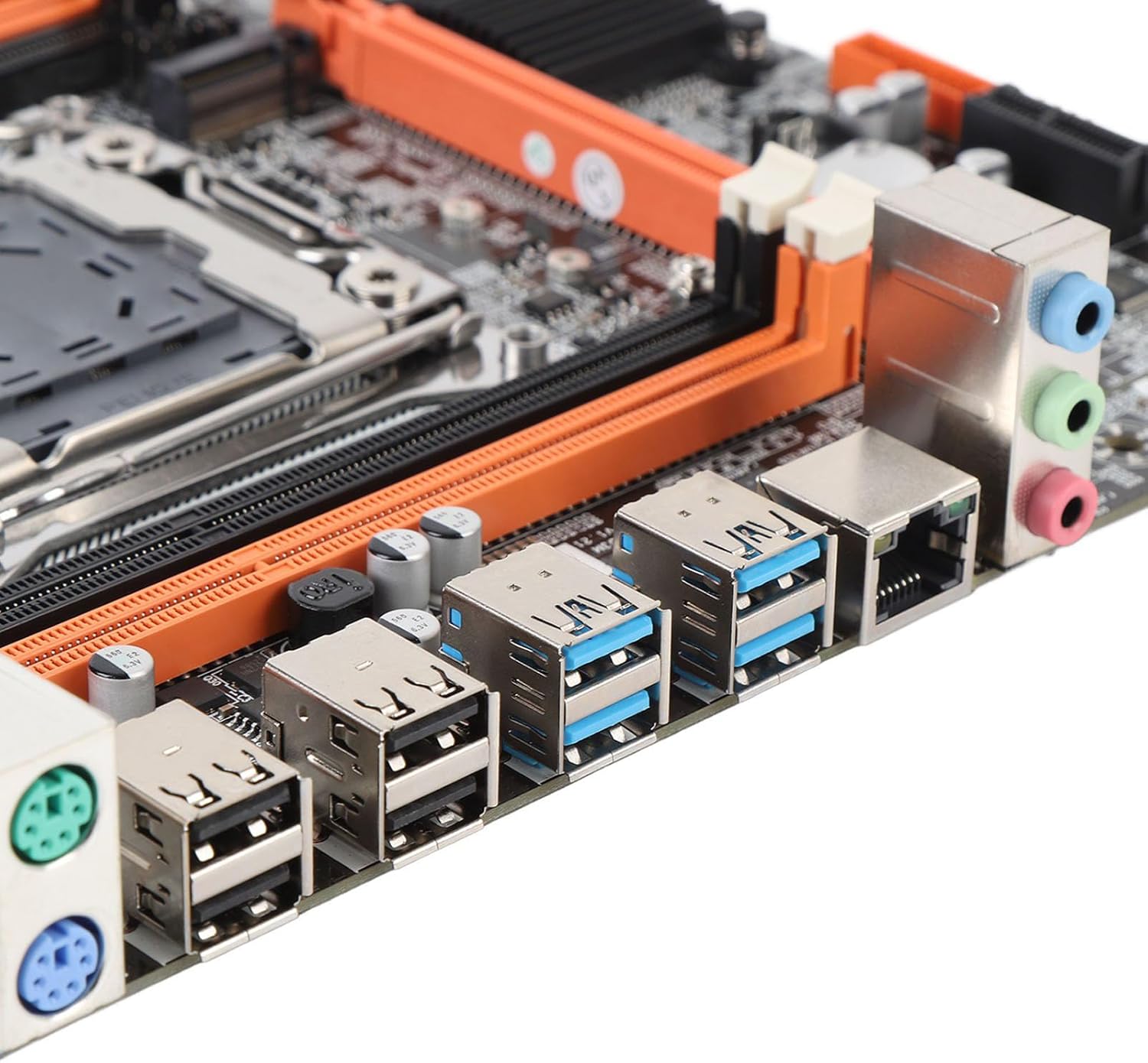
Image 4.4: Rear I/O ports including USB, LAN, and audio jacks. This image shows the external connectivity options available on the motherboard.
5. Instruções de operação
5.1. Inicialização
- After completing all hardware installations, connect your monitor, keyboard, and mouse.
- Power on your system. The system should display the BIOS/UEFI splash screen.
- Pressione a tecla designada (normalmente DEL or F2) during boot to enter the BIOS/UEFI setup.
5.2. Configuração da BIOS/UEFI
In the BIOS/UEFI, you can configure various system settings, including boot order, date/time, and hardware parameters. Ensure your boot device (e.g., SSD with OS) is prioritized in the boot sequence.
5.3. Instalação do driver
After installing your operating system, install the necessary drivers for the motherboard chipset, network, audio, and any other integrated components. These drivers are typically provided on a CD/DVD or can be downloaded from the manufacturer's website.
6. Especificações
| Tipo de item | Placa-mãe |
| Arquitetura da placa-mãe | M ATX |
| Chipset | X99H |
| Supported CPU Types | for LGA 2011-3 (E5 V3/V4, i7 58xx/68xx) |
| Tipo de memória | DDR4 2666, 2400, 2133MHz |
| Slots de memória | 4 × DDR4 DIMM (Max 128GB) |
| Onboard Network Card | Sim |
| Graphics Card Standard | PCI Express 16X |
| Portas USB | 4 2.0 x USB, 4 3.0 x USB |
| Serial ATA Ports | 4 x Serial ATA 2.0 |
| Bateria embutida | CR2032 x 1 (240mAh) |
| Slots de expansão | 1 x PCIE x16, 1 x PCIE X1, 1 x NVME M.2 Interface |
| Portas de E/S | PS/2, 1 x RJ45, USB 2.0, USB 3.0, Audio |
| Dimensões do produto | 10.24 x 7.87 x 1.97 polegadas |
| Peso do item | 1.46 libras |
| Número do modelo | Denashckge97d20i |
7. Solução De Problemas
- Sem energia: Ensure all power cables (24-pin ATX, 8-pin CPU) are securely connected to the motherboard and power supply. Verify the power supply switch is on.
- Nenhuma exibição: Check that the monitor is connected to the graphics card (not the motherboard's I/O if a dedicated GPU is installed). Reseat the graphics card and RAM modules.
- Instabilidade/travamentos do sistema: This can be caused by incompatible RAM, insufficient power, or overheating. Verify RAM compatibility and seating. Check CPU cooler installation and fan operation.
- Periférico não detectado: Ensure USB devices are properly connected. Try different USB ports. Check for necessary drivers.
- Reinicialização da BIOS: If system settings become unstable, you can clear the CMOS by removing the CR2032 battery for a few minutes or using the CMOS clear jumper (refer to motherboard diagram for location).
8. Manutenção
- Limpeza: Limpe regularmente a poeira da placa-mãe e dos componentes usando ar comprimido. Certifique-se de que o sistema esteja desligado e desconectado da tomada antes de realizar a limpeza.
- Atualizações de BIOS/UEFI: Verifique periodicamente as instruções do fabricante. website for BIOS/UEFI updates. Updates can improve stability, compatibility, and performance. Follow the update instructions carefully to avoid damaging the motherboard.
- Gerenciamento de cabos: Certifique-se de que os cabos estejam bem encaminhados para melhorar o fluxo de ar e evitar interferências.
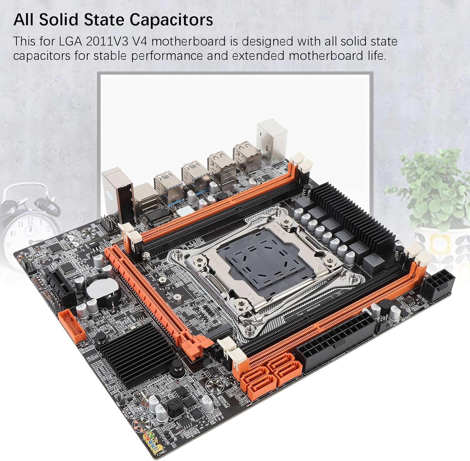
Image 8.1: Close-up of solid-state capacitors. These components contribute to the motherboard's stable performance and longevity.
9. Garantia e Suporte
For warranty information and technical support, please refer to the documentation provided with your purchase or visit the official Denash website. Guarde o comprovante de compra para solicitações de garantia.