1. Introdução
This manual provides detailed instructions for the installation, operation, and maintenance of your GODIYMODULES Audio Level Indicator VU Meter. This device is designed to visually represent audio levels through a 32-segment LED display, suitable for integration with car MP3 players, amplifiers, and other audio systems. Please read this manual thoroughly before use to ensure proper functionality and safety.
2. Produto acabadoview
The GODIYMODULES Audio Level Indicator features a compact design with a 32-segment LED display, offering multiple visual modes to enhance your audio experience. It includes connection points for power and audio input, along with adjustable sensitivity controls.

Figura 2.1: Frente view of the Audio Level Indicator with included wiring harness. This image shows the LED display segments, control button, sensitivity potentiometers, and the power/signal input connector with attached wires.
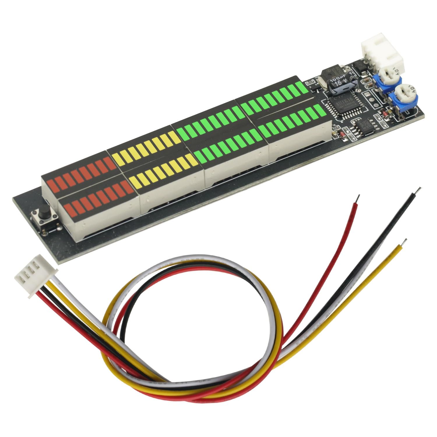
Figura 2.2: Traseira view of the Audio Level Indicator's Printed Circuit Board (PCB). This view highlights the solder points and component layout on the reverse side of the module, including labels for IN-L, IN-R, GND, and VCC connections.
3. Especificações
| Recurso | Detalhe |
|---|---|
| Volumetage | DC 6-16V |
| Atual (Espera) | 20 mA |
| Tipo de exibição | 32-segment LED Audio Indicator |
| Cores LED | Verde, amarelo, vermelho |
| Tamanho geral | 117 mm x 29 mm |
| Tamanho da tela | 82 mm x 10 mm |
| Material | PCB |
4. Instruções de Instalação e Conexão
Proper wiring is essential for the correct operation of the Audio Level Indicator. Refer to the diagram below and the detailed instructions for connecting the module to your audio system.

Figura 4.1: Wiring diagram illustrating power and audio signal connections, along with a visual representation of the adjustable display effects.
4.1. Power and Signal Connections
- Fio vermelho: Connect to power positive (DC 6-16V). For car installations, this is typically connected to the car's 12V power positive (e.g., ACC fuse box).
- Fio preto: Connect to power negative (ground).
- Fio amarelo: Connect to the right channel audio input (speaker +).
- Fio branco: Connect to the left channel audio input (speaker +).
4.2. Audio Signal Input Recommendations
For optimal performance, it is recommended to connect the audio signal to the front level (pré-amplifier output, such as from a computer or mobile phone). Connecting to the back level (amplifier output to speakers) is also possible, but be aware that the display effect may vary depending on the frequency range (treble, mid-range, bass) of the connected speaker output. For example, connecting to a treble output might not display bass instrument sounds, and connecting to a bass output might not display vocal sounds.
4.3. Dual Channel Flashing
- For both channels to flash together (mono effect): Twist the yellow and white wires together and connect them to a single speaker's positive (+) terminal.
- For independent left and right channel flashing (stereo effect): Connect the yellow wire to the positive (+) terminal of the right channel speaker and the white wire to the positive (+) terminal of the left channel speaker.
5. Instruções de operação
5.1. Modos de exibição
The Audio Level Indicator features multiple display modes, which can be cycled through using the button located on the module. The available modes are:
- Pico para baixo
- Peak up
- Center to sides with no peaks
- No peak inward on both sides
- Sem picos
- Alternating modes 1-5 every 24 seconds
Press the button briefly to switch between these display effects.
5.2. Ajuste de Sensibilidade
The module includes adjustable potentiometers (small rotary knobs) to fine-tune the sensitivity of the LED display. Use a small screwdriver to carefully adjust these knobs to achieve the desired response to your audio input level.
6. Solução De Problemas
- Sem exibição ou exibição parcial:
- Check power connections (red and black wires) for correct polarity and secure contact.
- Verifique o volume de entradatage is within the DC 6-16V range.
- Ensure audio signal wires (yellow and white) are correctly connected to the speaker positive terminals or pre-ampsaída mais vital.
- Adjust sensitivity potentiometers; they might be set too low.
- Display not responding to audio:
- Confirm audio source is active and producing sound.
- Recheck audio signal wire connections.
- Increase sensitivity using the adjustment knobs.
- If connected to speaker output, try connecting to a full-range signal or pre-amplifier output for a more consistent display.
- One channel not flashing:
- Verify the connection of the specific channel's audio input wire (yellow for right, white for left).
- Ensure the audio source is providing a signal to both channels.
7. Manutenção
The GODIYMODULES Audio Level Indicator is designed for low maintenance. Keep the unit clean and free from dust. Avoid exposing it to excessive moisture or extreme temperatures. Do not attempt to disassemble the unit beyond what is necessary for installation, as this may void any potential warranty and could damage the sensitive electronic components.
8. Garantia e Suporte
Specific warranty information for this product is not provided in this manual. For warranty claims, technical support, or further assistance, please contact your retailer or the manufacturer, GODIYMODULES, through their official support channels.