1. Introdução
The Velleman DVM810 is a compact and economical 3 1/2 digit digital multimeter designed for measuring DC and AC voltages, DC currents, resistance, and for performing diode and transistor (hFE) tests. It features overload protection and automatic polarity indication, making it suitable for hobbyists, field use, and workshops. This manual provides essential information for the safe and effective operation of your DVM810 multimeter.
2. Recursos do Produto
- Automatic polarity indication
- Volumetage measurements: AC 500V and DC 500V maximum
- Current measurements: DC 10A maximum (0.2A fused, 10A unfused)
- Resistance measurements: Up to 2MΩ
- Diode and transistor (hFE) test functions
- Proteção contra sobrecarga
- Compact design with 3 1/2 digit LCD display
3. Conteúdo da embalagem
Por favor, verifique o conteúdo da embalagem para garantir que todos os itens estejam presentes:
- Multímetro Digital Velleman DVM810
- Cabos de teste (um vermelho, um preto)
- Manual de instruções
4. Informações importantes de segurança
Read all safety warnings and instructions carefully before using this product. Failure to follow these instructions may result in electric shock, fire, or serious injury.
- Sempre verifique se o multímetro está configurado com a função e a escala corretas antes de realizar qualquer medição.
- Never exceed the maximum input limits for any range. The maximum voltage for AC/DC is 500V.
- Do not attempt to measure current on circuits with voltages superior a 250V.
- Inspecione os cabos de teste quanto a isolamento danificado ou metal exposto antes de cada utilização. Substitua os cabos danificados imediatamente.
- Do not use the multimeter if it appears damaged or if the case is open.
- Exercise extreme caution when working with live circuits. Use appropriate personal protective equipment.
- Desligue sempre a alimentação do circuito e descarregue os dispositivos de alta tensão.tage capacitors before measuring resistance or performing diode/transistor tests.
- Replace the battery when the low battery indicator appears on the display to ensure accurate readings.
5. Produto acabadoview
Familiarize yourself with the components of your Velleman DVM810 multimeter:
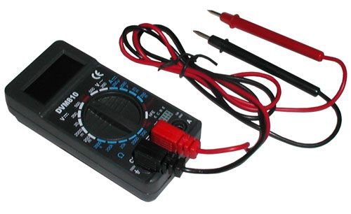
Figure 1: Velleman DVM810 Digital Multimeter. This image displays the front view of the compact multimeter, highlighting its liquid crystal display (LCD), the central rotary function switch, and the input jacks for test leads at the bottom.
- Tela LCD: Shows measurement readings, units, and polarity.
- Interruptor rotativo: Utilizado para selecionar a função e o intervalo de medição desejados.
- Jacks de entrada:
- Jack COM: Common (negative) input for all measurements. Connect the black test lead here.
- VΩmA Jack: Entrada positiva para voltage, resistance, and current measurements up to 200mA. Connect the red test lead here.
- 10A Jack: Positive input for high current measurements (up to 10A). Connect the red test lead here for 10A measurements.
- Cabos de teste: Red and black leads used to connect the multimeter to the circuit under test.
6. Configuração
6.1 Instalação da bateria
The DVM810 multimeter requires a 9V battery (not always included). To install or replace the battery:
- Ensure the multimeter is turned OFF (rotary switch set to OFF).
- Localize a tampa do compartimento da bateria na parte traseira da unidade.
- Remove the screw(s) securing the cover and carefully lift it off.
- Conecte uma bateria nova de 9V ao terminal da bateria, observando a polaridade correta.
- Coloque a bateria no compartimento e recoloque a tampa, fixando-a com o(s) parafuso(s).
6.2 Conectando os Cabos de Teste
Always connect the test leads correctly for accurate and safe measurements:
- Insira a ponta de prova preta no COM (comum) jack.
- Para a maioria das medições (vol.)tage, resistance, diode, hFE, and current up to 200mA), insert the red test lead into the VΩmA Jack.
- Para medições de alta corrente (até 10 A), insira o cabo de teste vermelho no... 10A Jack.
7. Instruções de operação
Before making any measurement, ensure the test leads are correctly connected and the rotary switch is set to the appropriate function and range.
7.1 Medição de Vol DCtage (V=)
- Insira o fio vermelho no VΩmA jack and the black lead into the COM Jack.
- Ajuste a chave rotativa para o volume CC desejado.tage (V=) range. Start with the highest range if the voltage é desconhecido.
- Connect the test leads across the component or circuit to be measured (in parallel).
- Leia o vol.tage value on the LCD display. The display will show the correct polarity.
7.2 Medição de Vol CAtage (V~)
- Insira o fio vermelho no VΩmA jack and the black lead into the COM Jack.
- Ajuste a chave rotativa para a tensão CA desejada.tage (V~) range. Start with the highest range if the voltage é desconhecido.
- Connect the test leads across the component or circuit to be measured (in parallel).
- Leia o vol.tage valor no display LCD.
7.3 Medição de corrente contínua (A=)
Caution: Never connect the multimeter in parallel with a voltage source when measuring current, as this can blow the fuse or damage the meter.
- Determine the expected current. For currents up to 200mA, insert the red lead into the VΩmA conector. Para correntes de até 10 A, insira o fio vermelho no 10A jack. Always insert the black lead into the COM Jack.
- Set the rotary switch to the appropriate DC Current (A=) range. Start with the highest range if the current is unknown.
- Turn off power to the circuit. Open the circuit where the current is to be measured.
- Conecte o multímetro em série com o circuito.
- Restore power to the circuit and read the current value on the LCD display.
7.4 Medição da resistência (Ω)
Caution: Ensure the circuit is completely de-energized and all capacitors are discharged before measuring resistance.
- Insira o fio vermelho no VΩmA jack and the black lead into the COM Jack.
- Set the rotary switch to the desired Resistance (Ω) range. Start with a higher range if the resistance is unknown.
- Conecte os cabos de teste ao componente que será medido.
- Leia o valor da resistência no visor LCD.
7.5 Teste de Diodo
Caution: Ensure the diode is disconnected from the circuit or the circuit is de-energized before testing.
- Insira o fio vermelho no VΩmA jack and the black lead into the COM Jack.
- Set the rotary switch to the Diode symbol (→|).
- Conecte o fio vermelho ao ânodo e o fio preto ao cátodo do diodo. O visor mostrará a tensão direta.tagqueda de tensão (tipicamente de 0.5V a 0.8V para diodos de silício).
- Reverse the leads. The display should show 'OL' (Overload) for a good diode. If it shows a reading in both directions or 'OL' in both directions, the diode may be faulty.
7.6 Teste do transistor (hFE)
Caution: Ensure the transistor is disconnected from the circuit before testing.
- Insira o fio vermelho no VΩmA jack and the black lead into the COM Jack.
- Coloque a chave rotativa na posição hFE.
- Identify if the transistor is NPN or PNP. Insert the transistor's emitter, base, and collector leads into the corresponding holes in the hFE socket on the multimeter.
- Leia o valor de hFE (ganho de corrente CC) no visor LCD.
8. Especificações
| Parâmetro | Valor |
|---|---|
| Marca | Velleman |
| Número do modelo | DVM810 |
| Tipo de medição | Multímetro |
| Vol. DCtage Alcance | Até 500V |
| Vol. CAtage Alcance | Até 500V |
| Faixa de corrente DC | Up to 10A (0.2A fused, 10A unfused) |
| Faixa de resistência | Até 2MΩ |
| Teste de diodo | Sim |
| Teste de transistor (hFE) | Sim |
| Mostrar | 3 1/2 Digit LCD |
| Fonte de energia | Bateria de 9V (não incluída) |
| Dimensões | Aproximadamente 3.70" x 1.81" x 1.03" |
| Peso do item | Aproximadamente 3.2 onças (0.2 libras) |
| UPC | 836479002272 |
9. Manutenção
9.1 Substituição da bateria
When the low battery indicator appears on the LCD, replace the 9V battery as described in Section 6.1. A weak battery can lead to inaccurate readings.
9.2 Limpeza
Para limpar o multímetro, limpe a carcaça com um pano úmido.amp cloth and a mild detergent. Do not use abrasives or solvents. Ensure the unit is completely dry before use.
9.3 Inspeção de Cabos de Teste
Regularly inspect the test leads for any signs of damage, such as cracked insulation, exposed wires, or loose connections. Replace damaged leads immediately to prevent electric shock hazards.
10. Solução De Problemas
- Sem imagem ou imagem muito fraca: Verifique a bateria. Substitua-a se necessário.
- Leituras incorretas:
- Certifique-se de que a chave rotativa esteja configurada para a função e faixa corretas.
- Verifique o volume da bateriatage; replace if low.
- Certifique-se de que os cabos de teste estejam conectados corretamente e não estejam danificados.
- For resistance measurements, ensure the circuit is de-energized.
- 'OL' (Sobrecarga) exibido: O valor medido excede o intervalo selecionado. Selecione um intervalo maior ou verifique se o circuito está dentro das capacidades do medidor.
- Fuse blown (during current measurement): If the meter stops measuring current, the internal fuse may have blown. Refer to a qualified technician for fuse replacement.
11. Garantia e Suporte
Warranty information for the Velleman DVM810 Digital Multimeter is typically provided with your purchase documentation or can be found on the official Velleman website. For technical support, service, or further inquiries, please refer to the contact information provided by your retailer or the manufacturer's official support channels.


