1. Introdução
Thank you for choosing the Voltcraft VC-11 Digital Multimeter. This portable, Category III, 250V multimeter with a 2000-count display is designed for accurate electrical measurements in various applications. This manual provides essential information for safe operation, proper use, and maintenance of your device. Please read it thoroughly before use and keep it for future reference.
2. Informações de segurança
WARNING: Electrical shock hazard. Improper use of this meter can cause damage, shock, injury, or death. Read and understand this manual before operating the meter.
- Always ensure the meter is in good working condition and the test leads are not damaged.
- Não aplique mais do que o volume nominaltage, as marked on the meter, between terminals or between any terminal and ground.
- Tenha extremo cuidado ao trabalhar com voltages above 25V AC RMS or 35V DC. These voltagrepresentam um risco de choque.
- Sempre desconecte os cabos de teste do circuito antes de alterar as funções ou as faixas de medição.
- Do not operate the meter with the battery cover removed or loosened.
- Adhere to local and national safety codes. Use personal protective equipment (PPE) such as approved safety glasses and electrically insulated gloves.
3. Produto acabadoview
The Voltcraft VC-11 is a compact digital multimeter featuring a clear LCD display, a rotary function switch, and input jacks for test leads. It is designed for measuring DC/AC voltage, DC current, resistance, and includes diode and continuity test functions.
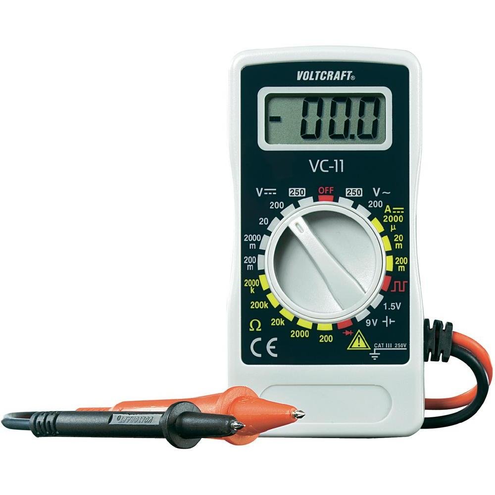
Figura 1: Frente view of the Voltcraft VC-11 Digital Multimeter with test leads connected. This image shows the LCD display, rotary switch, and input terminals.

Figura 2: Angulado view of the Voltcraft VC-11 Digital Multimeter, highlighting the compact design and the CE marking.

Figure 3: The Voltcraft VC-11 Digital Multimeter shown with its test leads detached, illustrating the input ports.
3.1 Componentes
- Tela LCD: Exibe leituras de medição, unidades e indicadores de função.
- Interruptor rotativo: Used to select measurement functions and ranges.
- Jacks de entrada: Ports for connecting the test leads (COM, VΩmA).
- Cabos de teste: Red and black leads for connecting to the circuit under test.
4. Configuração
4.1 Instalação da bateria
The Voltcraft VC-11 requires a 9V battery for operation (not included). To install or replace the battery:
- Certifique-se de que o multímetro esteja desligado e desconecte todos os cabos de teste.
- Localize a tampa do compartimento da bateria na parte traseira do medidor.
- Use uma chave de fenda para remover o parafuso que prende a tampa da bateria.
- Remova a tampa com cuidado.
- Conecte uma bateria nova de 9V ao terminal da bateria, observando a polaridade correta.
- Coloque a bateria no compartimento e recoloque a tampa, fixando-a com o parafuso.
4.2 Conectando os Cabos de Teste
Always connect the black test lead to the 'COM' (common) jack. Connect the red test lead to the appropriate input jack based on the desired measurement:
- para voltage (V), Resistance (Ω), Diode, and Continuity measurements, connect the red lead to the 'VΩmA' jack.
- For Current (A) measurements, connect the red lead to the 'VΩmA' jack (for mA range).
5. Instruções de operação
Before taking any measurement, ensure the test leads are correctly connected and the rotary switch is set to the desired function and range.
5.1 Medição de Vol DCtage (V=)
- Ajuste a chave rotativa para o volume CC desejado.tage (V=) range (e.g., 200mV, 2V, 20V, 200V, 250V). If the voltagSe e for desconhecido, comece com o intervalo mais alto e diminua conforme necessário.
- Connect the black test lead to the 'COM' jack and the red test lead to the 'VΩmA' jack.
- Conecte as pontas de prova em paralelo ao componente ou circuito a ser medido.
- Leia o vol.tage valor no display LCD.
5.2 Medição de Vol CAtage (V~)
- Ajuste a chave rotativa para a tensão CA desejada.tage (V~) faixa (ex.: 200V, 250V).
- Connect the black test lead to the 'COM' jack and the red test lead to the 'VΩmA' jack.
- Conecte as pontas de prova em paralelo à fonte de alimentação CA ou ao componente.
- Leia o vol.tage valor no display LCD.
5.3 Medição de corrente contínua (A=)
- Set the rotary switch to the desired DC Current (A=) range (e.g., 2000µA, 20mA, 200mA).
- Connect the black test lead to the 'COM' jack and the red test lead to the 'VΩmA' jack.
- AVISO: To measure current, the meter must be connected in series with the circuit. Break the circuit and insert the meter.
- Connect the test probes in series with the circuit.
- Leia o valor atual no visor LCD.
5.4 Medição da resistência (Ω)
- Certifique-se de que o circuito esteja desenergizado antes de medir a resistência.
- Set the rotary switch to the desired Resistance (Ω) range (e.g., 200Ω, 2kΩ, 20kΩ, 200kΩ, 2000kΩ).
- Connect the black test lead to the 'COM' jack and the red test lead to the 'VΩmA' jack.
- Conecte as pontas de prova ao componente que deseja medir.
- Leia o valor da resistência no visor LCD.
5.5 Teste de Diodo
- Certifique-se de que o circuito esteja desenergizado.
- Set the rotary switch to the Diode symbol (usually next to resistance).
- Connect the black test lead to the 'COM' jack and the red test lead to the 'VΩmA' jack.
- Conecte a ponta de prova vermelha ao ânodo e a ponta de prova preta ao cátodo do diodo. O visor mostrará a tensão direta.tage gota.
- Inverta as pontas de prova. O visor deve mostrar 'OL' (Sobrecarga) para um diodo em bom estado.
5.6 Teste de Continuidade
- Certifique-se de que o circuito esteja desenergizado.
- Set the rotary switch to the Continuity symbol (usually next to diode/resistance).
- Connect the black test lead to the 'COM' jack and the red test lead to the 'VΩmA' jack.
- Conecte as pontas de prova ao circuito ou componente.
- If the resistance is below a certain threshold (typically 30-50Ω), the meter will emit an audible beep, indicating continuity.
6. Manutenção
6.1 Limpeza
Limpe o medidor com anúncios.amp Use um pano e um detergente suave. Não utilize abrasivos ou solventes. Certifique-se de que o medidor esteja completamente seco antes de usar.
6.2 Substituição da bateria
When the battery symbol appears on the LCD display, the 9V battery needs to be replaced. Refer to section 4.1 for battery installation instructions.
7. Solução De Problemas
| Problema | Possível causa | Solução |
|---|---|---|
| Sem imagem ou imagem fraca | Bateria descarregada ou fraca | Substitua a bateria de 9V. |
| Leituras incorretas | Incorrect function/range selected Conexão ruim do cabo de teste Cabos de teste danificados | Select the correct function and range. Ensure test leads are firmly connected. Inspect and replace damaged test leads. |
| "OL" (Sobrecarga) exibido | A medição excede o intervalo selecionado. Open circuit (for resistance/current) | Select a higher range. Check for breaks in the circuit. |
8. Especificações
- Marca: VOLTCRAFT
- Número do modelo: VC11
- Fabricante: VOLTCRAFT
- Peso do produto: Approximately 9.07 g (without packaging)
- Dimensões da embalagem: 14.8 x 8 x 3.6 cm
- Classificação da categoria: CATIII 250V
- Mostrar: 2000 contagens
- Fonte de energia: Bateria de 9V (não incluída)
9. Informações de garantia
This product is covered by a standard manufacturer's warranty. Please refer to the warranty card included with your purchase or contact your retailer for specific terms and conditions. The warranty typically covers defects in materials and workmanship under normal use.
10. Suporte ao cliente
For technical assistance, troubleshooting, or service inquiries, please contact Voltcraft customer support or your local distributor. Contact information can usually be found on the manufacturer's website ou na embalagem do produto.


