Introdução
The Intermatic ET9250 is a 4-circuit relay module designed for use with the Intermatic ET90000 series controllers. This module serves as a replacement part or an upgrade component, allowing for the expansion of the controller's circuit capacity. Each ET9250 module includes four SPDT (Single Pole Double Throw) 30 amp relays, facilitating robust control over various electrical loads.
Informações importantes de segurança
Please read and understand all instructions before installing or operating this device. Failure to follow these instructions could result in property damage, personal injury, or death.
- Desconecte a energia: Always disconnect power at the circuit breaker or fuse box before installing or servicing this module.
- Pessoal qualificado: Installation and servicing should only be performed by qualified electrical personnel.
- Códigos locais: Toda a fiação deve estar em conformidade com as normas elétricas nacionais e locais.
- Uso adequado: Do not use this module for purposes other than those specified in this manual.
- Condições ambientais: Ensure the module is installed in an environment free from excessive moisture, dust, and extreme temperatures.
Produto acimaview
The ET9250 module is a compact circuit board designed to integrate seamlessly with compatible Intermatic ET90000 series controllers. It provides additional switching capabilities for your system.
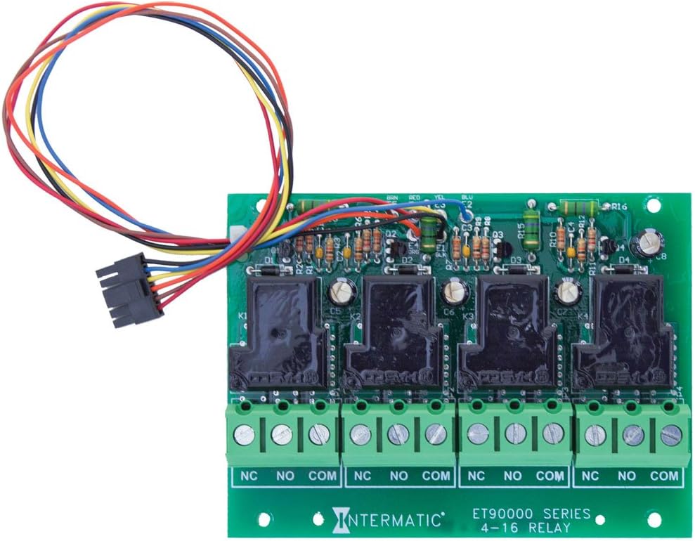
Os principais componentes incluem:
- Four SPDT 30 Amp Relés: These relays (K1-K4) are the primary switching components, capable of handling loads up to 30 amps.
- Blocos de terminais: Screw terminals for connecting external loads, clearly marked NC, NO, and COM for each circuit.
- Chicote de Fios: A multi-colored wire harness for connecting the module to the main ET90000 series controller.
Instalação e configuração
The ET9250 relay module is designed for integration with specific Intermatic ET90000 series controllers, including models such as ET90415CR, ET98015CR, ET91215CR, and ET91615CR. It comes in 4-circuit packs, allowing for system expansion up to a maximum of 16 circuits.
Etapas de instalação:
- Desconexão de energia: Ensure all power to the ET90000 series controller is disconnected at the main circuit breaker before beginning installation.
- Access Controller: Open the ET90000 series controller enclosure to access the internal components.
- Colocação do módulo: Carefully align the ET9250 module with the designated expansion slot or mounting points within the controller.
- Connect Wire Harness: Connect the multi-colored wire harness from the ET9250 module to the corresponding connector on the main controller board. Ensure a secure and correct connection.
- Módulo seguro: Secure the module in place using any provided fasteners or clips.
- Wiring Loads: Connect the electrical loads to the NC, NO, and COM terminals on the ET9250 module as required by your application. Refer to the specific wiring diagram for your ET90000 series controller for detailed instructions.
- Recinto Fechado: Once all connections are made and verified, close the controller enclosure.
- Restaurar energia: Restore power to the controller at the main circuit breaker.
- Configuração de Sistema: Follow the instructions in your ET90000 series controller manual to configure the newly added circuits.
Operação
The ET9250 relay module operates under the control of the main ET90000 series controller. Each of the four SPDT 30 amp relays can be programmed and controlled independently by the timer or automation functions of the primary unit. When the controller sends a signal, the corresponding relay will switch, opening or closing the circuit to which it is connected. This allows for automated control of various electrical devices or systems.
Manutenção
The Intermatic ET9250 relay module is designed for reliable, long-term operation with minimal maintenance. However, periodic inspection can help ensure continued performance.
- Inspeção visual: Annually inspect the module and its connections for any signs of damage, corrosion, or loose wiring.
- Limpeza: Keep the controller enclosure clean and free of dust and debris, which can impede proper operation and heat dissipation.
- Proteção Ambiental: Ensure the module remains protected from moisture and extreme temperatures as per its operating specifications.
- Desconexão de energia: Always disconnect power before performing any inspection or cleaning.
Solução de problemas
If you experience issues with your ET9250 relay module, consider the following troubleshooting steps:
- Sem energia para carregar: Verify that the main controller is receiving power and is programmed correctly. Check the wiring connections to the ET9250 module and the load for looseness or damage.
- Incorrect Switching: Ensure the programming in the main ET90000 series controller is correct for the desired switching action. Check for any error codes or indicators on the main controller.
- Módulo não reconhecido: If the main controller does not recognize the newly installed module, ensure the wire harness is securely connected and that the module is properly seated. Refer to the main controller's manual for module detection procedures.
- Sobrecarga: If a relay is not switching or appears damaged, check the connected load to ensure it does not exceed the 30 amp rating of the relay.
- Assistência profissional: For persistent issues or if you are unsure about any troubleshooting steps, contact a qualified electrician or Intermatic customer support.
Especificações técnicas
| Especificação | Detalhe |
|---|---|
| Número do modelo | ET9250 |
| Marca | Intermatic |
| Tipo de contato | SPDT (Polo Simples, Duplo Lançamento) |
| Classificação atual | 30 Amps |
| Corrente máxima de comutação | 30 Amps |
| Número de Circuitos | 4 |
| Tipo de montagem | Surface Mount (within controller) |
| Modo de operação | Automatic (controlled by main unit) |
| Dimensões do produto | 5 x 3.75 x 1.25 polegadas |
| Peso do item | 4.8 onças |
| UPC | 078275127746 |
Informações de garantia
For detailed warranty information regarding the Intermatic ET9250 4-Circuit Relay Module, please refer to the manufacturer's official warranty description provided with your product or visit the Intermatic webOs termos e condições da garantia podem variar.
Suporte ao cliente
If you require further assistance, have questions about installation, operation, or troubleshooting that are not covered in this manual, please contact Intermatic customer support. You can typically find contact information on the Intermatic website or within the documentation provided with your ET90000 series controller.


