1. Introdução
This manual provides essential information for the safe and effective installation, operation, and maintenance of the ABB B6-30-01-01 Compact 3-Pole Contactor. The B6-30-01-01 is a compact 3-pole contactor featuring one auxiliary contact and screw terminals, designed for reliable performance in applications where space is limited. It is suitable for controlling single or three-phase loads in residential, commercial, and industrial environments.
2. Informações de segurança
AVISO: Electrical shock hazard. Installation and maintenance should only be performed by qualified personnel. Disconnect all power before working on the contactor or connected equipment.
- Respeite sempre as normas e regulamentações elétricas locais e nacionais.
- Assegure-se de que todos os equipamentos estejam devidamente aterrados.
- Verifique se o voltagAs classificações de corrente e potência do contator correspondem aos requisitos da aplicação.
- Do not operate the contactor if it is damaged.
3. Produto acabadoview
The ABB B6-30-01-01 mini contactor is engineered for controlling various electrical loads. Key features include:
- Design compacto: Optimized for installations with limited space.
- Configuração de 3 polos: For switching three-phase loads.
- 1 Auxiliary Contact: One normally open (NO) auxiliary contact for control circuit applications.
- Terminais de parafuso: Secure and reliable electrical connections.
- Silent Coil: Garante um funcionamento silencioso.
- Switch Position Indication: Visual indication of the contactor's state.
- Opções de montagem: Integrated possibility for DIN rail or wall mounting.
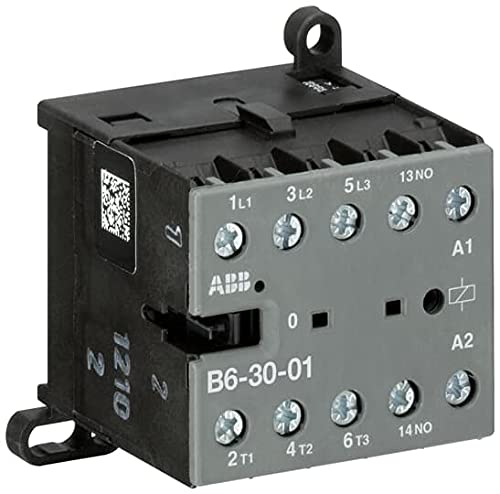
Figura 1: ABB B6-30-01-01 Compact Contactor. This image displays the grey and black casing of the contactor, clearly showing the screw terminals labeled 1L1, 3L2, 5L3 (inputs), 2T1, 4T2, 6T3 (outputs), A1, A2 (coil connections), and 13NO, 14NO (auxiliary contact). The ABB logo and a QR code are also visible on the unit.
4. Especificações
| Número do modelo | B6-30-01-01 (Manufacturer's Part Number: GJL1211001R0011) |
| Marca | FIG |
| Número de postes | 3 |
| Contatos Auxiliares | 1 Normalmente aberto (NÃO) |
| Tipo de terminal | Terminais de parafuso |
| Rated Operational Power (AC-3) | Até 4 kW |
| Rated Operational Current (AC-1) | 20 A / 690 V |
| Dimensões (aproximadas) | 2.16 x 2.16 x 1.96 polegadas (54.86 x 54.86 x 49.78 mm) |
| Peso (aproximado) | 4 onças (113 gramas) |
| Montagem | DIN Rail or Wall Mounting |
5. Instalação
Before beginning installation, ensure all power to the circuit is disconnected. The B6-30-01-01 contactor can be mounted on a standard DIN rail or directly to a panel using screws.
5.1. Montagem
- Montagem em trilho DIN: Align the contactor's integrated clips with the DIN rail and press firmly until it clicks into place.
- Montagem na parede: Use appropriate screws and anchors (not supplied) to secure the contactor through the designated mounting holes on the base. Ensure the mounting surface is stable and capable of supporting the contactor's weight and any connected wiring.
5.2. Considerações ambientais
Install the contactor in a clean, dry environment, free from excessive dust, moisture, corrosive gases, and extreme temperatures. Ensure adequate ventilation to prevent overheating.
6. Fiação
Refer to the wiring diagram provided with your specific application and ensure all connections are secure. Use appropriate wire gauges for the expected current load.
6.1. Power Circuit Connections
- Terminais de entrada: Connect the incoming power lines to terminals 1L1, 3L2, e 5L3.
- Terminais de saída: Conecte a carga aos terminais. 2T1, 4T2, e 6T3.
6.2. Control Circuit Connections
- Coil Terminals: Conecte o vol de controletage to terminals A1 e A2. Ensure the control voltage matches the coil voltage rating of the contactor.
- Contato auxiliar: The normally open (NO) auxiliary contact is connected to terminals 13NÃO e 14NÃO. This contact closes when the main coil is energized.
Tighten all screw terminals to the manufacturer's specified torque to ensure reliable electrical contact and prevent loose connections.
7. Operação
The ABB B6-30-01-01 contactor operates by energizing its coil. When the appropriate control voltage is applied to terminals A1 and A2, the coil creates a magnetic field, pulling the main contacts closed and connecting the power circuit from 1L1/3L2/5L3 to 2T1/4T2/6T3. Simultaneously, the auxiliary contact (13NO-14NO) will close.
- Energizando a bobina: Applying the rated control voltage to A1 and A2 will close the main and auxiliary contacts.
- Desenergizando a bobina: Removendo o controle voltage from A1 and A2 will cause the coil to de-energize, opening the main and auxiliary contacts.
- Switch Position Indication: A visual indicator on the contactor provides feedback on the current state of the main contacts (e.g., '0' for open, 'I' for closed, or a similar marking).
8. Manutenção
A manutenção regular ajuda a garantir a longevidade e o funcionamento confiável do contator. Sempre desligue a energia antes de realizar qualquer manutenção.
- Inspeção visual: Periodically inspect the contactor for any signs of damage, discoloration, loose connections, or excessive dust accumulation.
- Limpeza: Use a dry, soft cloth or compressed air to remove dust and debris from the contactor's exterior. Do not use solvents or abrasive cleaners.
- Aperto terminal: Check and re-tighten all screw terminals as necessary to prevent overheating due to loose connections.
- Lentes de contato: While internal contacts are generally not user-serviceable, excessive arcing or contact welding may indicate a need for replacement.
9. Solução De Problemas
Se o contator não estiver funcionando como esperado, considere os seguintes problemas comuns:
- O contator não energiza:
- Verifique se o volume de controletage is present at terminals A1 and A2.
- Verify the control voltage matches the coil's rated voltage.
- Inspect control circuit wiring for loose connections or breaks.
- Contactor Energizes But Load Does Not Receive Power:
- Ensure main power is supplied to 1L1, 3L2, 5L3.
- Check connections to the load at 2T1, 4T2, 6T3.
- Verify the contactor's switch position indicator shows 'closed'.
- Superaquecimento:
- Verifique se há conexões de terminal soltas.
- Ensure the load current does not exceed the contactor's ratings.
- Verifique se há ventilação adequada ao redor do contator.
If issues persist after troubleshooting, contact qualified electrical personnel or ABB technical support.
10. Informações de garantia
Specific warranty terms and conditions for the ABB B6-30-01-01 contactor are provided by ABB at the time of purchase. Please refer to the documentation included with your product or visit the official ABB webPara informações detalhadas sobre a garantia, consulte o site. Guarde o comprovante de compra para eventuais solicitações de garantia.
11. Suporte Técnico
For technical assistance, product inquiries, or service, please contact ABB customer support. Contact information can typically be found on the official ABB website or through your local ABB distributor.
ABB Official Website: www.abb.com


