1. Introdução
This manual provides essential information for the proper setup, operation, and maintenance of the CC1101TR4S Wireless Transceiver Module. This module is designed for reliable wireless communication in various applications, supporting multiple frequency bands and modulation methods.
2. Produto acabadoview
The CC1101TR4S is a versatile wireless transceiver module capable of operating at 433MHz and 868MHz, with customization options for 315MHz and 915MHz. It features efficient GFSK modulation, robust anti-interference capabilities, and built-in hardware CRC error detection, making it suitable for industrial control environments. The module supports FSK, GFSK, and MSK modulation methods and offers high receive sensitivity up to -110dBm at 1.2kbps.
Os principais recursos incluem:
- Frequências de operação: 433MHz / 868MHz (customizable to 315MHz / 915MHz).
- Vol operacionaltage: 3.3V.
- Maximum Operating Rate: 500 kbps.
- Modulation Methods: FSK, GFSK, MSK.
- Sensibilidade de recebimento: Up to -110dBm at 1.2kbps.
- Consumo atual: TX Mode (<30mA at +10dBm), RX Mode (20mA), Sleep Mode (1uA).
- Detecção de erro: Built-in hardware CRC.
- Suporte para antena: Spring antenna, rod antenna, whip antenna, RF interface cable (selection depends on application environment).
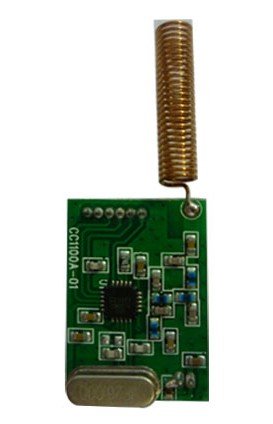
Figure 1: CC1101TR4S Wireless Transceiver Module. This image shows the compact module with its pin headers, ready for integration into a circuit board.
3. Especificações
| Recurso | Valor |
|---|---|
| Número do modelo | CC1101TR4S (Yu-szwx447) |
| Vol operacionaltage | 3.3V |
| Frequências de operação | 433MHz / 868MHz (Customizable 315M / 915M) |
| Max Operating Rate | 500 kbps |
| Modulation Methods | FSK, GFSK, MSK |
| Receber Sensibilidade | -110dBm (at 1.2kbps) |
| TX Mode Current (+10dBm) | < 30mA |
| RX Mode Current | 20mA |
| Corrente do modo de espera | 1uA |
| Module Dimensions (without antenna) | 23.4 x 16.3 mm |
| Pin Pitch | 1.27 milímetros |
| Peso do item | 1.1 pounds (approx. for lot) |
| Fabricante | Taida |
4. Configuração
Follow these steps to integrate and set up your CC1101TR4S module:
- Prepare Host System: Ensure your microcontroller or host system is ready to interface with the module via SPI (Serial Peripheral Interface).
- Conexão de energia: Connect the module's VCC pin to a stable 3.3V power supply and GND to ground. Ensure the power supply can provide the necessary current (up to 30mA during TX).
- SPI Interface: Connect the module's MOSI, MISO, SCK, and CSN pins to the corresponding SPI pins on your host system.
- GDO Pins: Connect the GDO0 and GDO2 pins to interrupt-capable pins on your host system if you plan to use interrupt-driven communication (e.g., for packet reception or clear channel assessment).
- Conexão da antena: Attach the appropriate antenna for your application and frequency band (e.g., 433MHz or 868MHz spring antenna). Ensure the antenna is securely connected to the module's RF output.
- Configuração de software: Initialize the CC1101 registers via SPI to set desired frequency, data rate, modulation type (GFSK, FSK, MSK), output power, and other parameters. Refer to the CC1101 datasheet for detailed register descriptions.
5. Instruções de operação
Once the module is set up and configured, you can begin transmitting and receiving data:
- Modo de transmissão:
- Write data to the TX FIFO buffer via SPI.
- Issue the STX (Start Transmit) command.
- The module will automatically transmit the data. Monitor GDO0/GDO2 for packet sent indication if configured.
- Modo de recepção:
- Issue the SRX (Start Receive) command.
- The module will enter receive mode and listen for incoming packets.
- When a packet is received, GDO0/GDO2 can signal an interrupt.
- Read data from the RX FIFO buffer via SPI.
- Frequency Hopping/Channel Switching: To change operating frequency or channel, update the frequency registers via SPI. Ensure both transmitting and receiving modules are synchronized to the same frequency.
- Gerenciamento de energia: Utilize the SLEEP and IDLE states to conserve power when the module is not actively transmitting or receiving.
6. Manutenção
The CC1101TR4S module is designed for robust operation with minimal maintenance. Adhere to the following guidelines:
- Condições ambientais: Operate the module within its specified temperature and humidity ranges. Avoid exposure to extreme temperatures, moisture, or corrosive environments.
- Manuseio Físico: Handle the module with care to prevent physical damage to components or solder joints. Avoid bending or stressing the antenna connection.
- Limpeza: If necessary, gently clean the module with a dry, soft cloth. Do not use liquid cleaners or solvents.
- Integridade da antena: Periodically check the antenna for damage or loose connections. A damaged antenna can significantly reduce performance.
7. Solução De Problemas
If you encounter issues with your CC1101TR4S module, consider the following common problems and solutions:
| Problema | Possível causa/solução |
|---|---|
| No communication between modules. |
|
| Poor range or intermittent connection. |
|
| Module not responding to SPI commands. |
|
8. Garantia e Suporte
Specific warranty information for this product is not provided in the available documentation. For warranty claims, technical support, or further assistance, please contact the seller or manufacturer directly. Ensure you have your purchase details and model number (CC1101TR4S / Yu-szwx447) ready when seeking support.


