1. Introdução
This manual provides essential instructions for the safe and effective use of your DT321B Digital Multimeter. This portable device is designed for measuring AC/DC voltage, DC current, resistance, and includes features for diode testing, continuity, battery testing, and transistor (hFE) measurements. Please read this manual thoroughly before operation and retain it for future reference.
2. Informações de segurança
Always observe basic safety precautions when using this multimeter to reduce the risk of fire, electric shock, or personal injury.
- Não aplicar voltage ou corrente que exceda os limites máximos especificados para o multímetro.
- Certifique-se de que os cabos de teste estejam em boas condições e devidamente conectados antes de realizar qualquer medição.
- Never use the multimeter if it appears damaged or if the test leads are damaged.
- Tenha cautela ao trabalhar com voláteis.tagacima de 30V AC RMS, 42V pico ou 60V DC. Essas tensõestagrepresentam um risco de choque.
- Always disconnect power to the circuit under test before measuring resistance or continuity.
- Não utilize o multímetro em atmosferas explosivas.
- Substitua as pilhas quando o indicador de bateria fraca acender para garantir leituras precisas.
3. Produto acabadoview
The DT321B Digital Multimeter features a clear LCD display and a rotary switch for selecting various measurement functions. Input jacks are provided for connecting test leads.

Figura 3.1: Frente view of the DT321B Digital Multimeter with key components labeled. The display shows numerical readings, the hold button freezes the current reading, and the rotary switch selects measurement functions. The '10A' jack is for high current measurements, 'COM' is the common ground, and 'VΩmA' is for voltage, resistência e medições de baixa corrente.
The multimeter includes a blue backlight for improved visibility in low-light conditions and a data hold function to freeze the displayed reading.
4. Configuração
4.1 Instalação da bateria
The DT321B Digital Multimeter requires two 1.5V batteries (Type 7, typically AAA) for operation. To install or replace batteries:
- Certifique-se de que o multímetro esteja desligado.
- Localize a tampa do compartimento da bateria na parte traseira da unidade.
- Desaperte o(s) parafuso(s) de fixação e remova a tampa.
- Insert the two 1.5V batteries, observing the correct polarity (+ and -) as indicated inside the compartment.
- Recoloque a tampa do compartimento da bateria e fixe-a com o(s) parafuso(s).
5. Instruções de operação
Before making any measurements, ensure the test leads are securely plugged into the correct input jacks.

Figure 5.1: The DT321B Multimeter with test probes connected. The black probe is connected to the 'COM' (common) jack, and the red probe is connected to the 'VΩmA' jack for most voltage, resistência e medições de baixa corrente.
5.1 Medição de Vol DCtage (V–)
- Insira o fio de teste vermelho no conector 'VΩmA' e o fio de teste preto no conector 'COM'.
- Ajuste a chave rotativa para o volume CC desejado.tage (V–) range (e.g., 200m, 2, 20, 200, 1000V). If the voltage is unknown, start with the highest range and work downwards.
- Conecte as pontas de prova nos terminais do componente ou circuito a ser medido.
- Leia o vol.tage valor no display LCD.
5.2 Medição de Vol CAtage (V∼)
- Insira o fio de teste vermelho no conector 'VΩmA' e o fio de teste preto no conector 'COM'.
- Ajuste a chave rotativa para a tensão CA desejada.tage (V∼) range (e.g., 200, 750V).
- Conecte as pontas de prova nos terminais do componente ou circuito a ser medido.
- Leia o vol.tage valor no display LCD.
5.3 Measuring DC Current (A–)
CUIDADO: To avoid damage to the multimeter or the circuit, never connect the test leads in parallel across a voltage source when measuring current. Always connect in series.
- For currents up to 200mA, insert the red test lead into the 'VΩmA' jack. For currents up to 10A, insert the red test lead into the '10A MAX' jack. The black test lead always goes into the 'COM' jack.
- Set the rotary switch to the desired DC Current (A–) range (e.g., 200u, 2m, 20m, 200m, 10A).
- Abra o circuito onde a corrente deve ser medida e conecte o multímetro em série com o circuito.
- Leia o valor atual no visor LCD.
5.4 Medição da resistência (Ω)
CUIDADO: Ensure the circuit under test is completely de-energized before measuring resistance.
- Insira o fio de teste vermelho no conector 'VΩmA' e o fio de teste preto no conector 'COM'.
- Set the rotary switch to the desired Resistance (Ω) range (e.g., 200, 2k, 20k, 200k, 2M).
- Conecte as pontas de prova ao componente que deseja medir.
- Leia o valor da resistência no visor LCD.
5.5 Teste de Diodo
- Insira o fio de teste vermelho no conector 'VΩmA' e o fio de teste preto no conector 'COM'.
- Set the rotary switch to the diode symbol (→|).
- Conecte a ponta de prova vermelha ao ânodo e a ponta de prova preta ao cátodo do diodo. O visor mostrará a tensão direta.tage gota.
- Inverta as pontas de prova. O visor deve mostrar 'OL' (circuito aberto) para um diodo em bom estado.
5.6 Teste de Continuidade
- Insira o fio de teste vermelho no conector 'VΩmA' e o fio de teste preto no conector 'COM'.
- Set the rotary switch to the continuity symbol (♫).
- Connect the test probes across the circuit or component. If continuity exists (resistance below a certain threshold), the buzzer will sound.
5.7 Battery Testing (1.5V / 9V)
- Insira o fio de teste vermelho no conector 'VΩmA' e o fio de teste preto no conector 'COM'.
- Set the rotary switch to the '1.5V BATT' or '9V BATT' position.
- Connect the red probe to the positive terminal and the black probe to the negative terminal of the battery.
- Leia o volume da bateriatage no visor.
5.8 Teste do transistor (hFE)
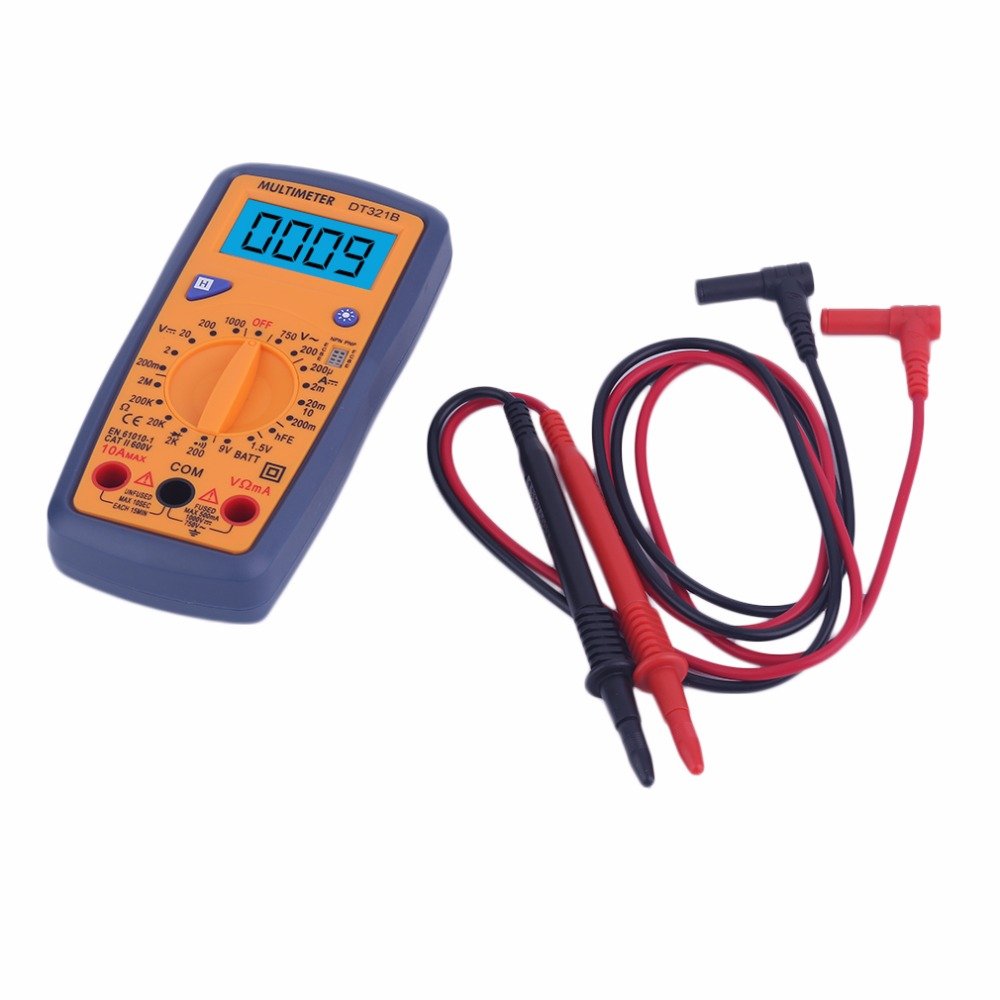
Figure 5.2: The DT321B Multimeter in use, with an inset showing a transistor being tested. The multimeter can measure the hFE (current gain) of NPN and PNP transistors.
- Coloque a chave rotativa na posição 'hFE'.
- Identify the NPN or PNP type of the transistor.
- Insert the transistor leads (Emitter, Base, Collector) into the corresponding sockets in the 'hFE' test socket on the multimeter.
- Read the hFE value on the LCD display.
5.9 Função de retenção de dados
Press the 'Hold' button to freeze the current reading on the display. Press it again to release the hold function and resume live readings.
5.10 Função de retroiluminação
The multimeter features a blue backlight. Press the backlight button (often integrated with the 'Hold' button or a separate button with a light symbol) to turn the backlight on or off for improved visibility.
6. Manutenção
6.1 Limpeza
Limpe a caixa com anúncioamp Limpe o multímetro com um pano e detergente neutro. Não utilize abrasivos ou solventes. Certifique-se de que o multímetro esteja completamente seco antes de usar.
6.2 Substituição da bateria
When the low battery symbol appears on the display, replace the batteries as described in Section 4.1. Remove batteries if the multimeter is not used for extended periods to prevent leakage.
7. Solução De Problemas
- Sem imagem ou imagem muito fraca: Verifique a instalação e a carga da bateria. Substitua as baterias, se necessário.
- Leituras incorretas: Ensure the rotary switch is set to the correct function and range. Check test lead connections. Verify the circuit under test is properly prepared (e.g., de-energized for resistance).
- 'OL' (Sobrecarga) exibido: O valor medido excede o intervalo selecionado. Alterne para um intervalo superior ou verifique se há um circuito aberto.
- No continuity buzzer: Ensure the multimeter is in continuity mode and the circuit is closed.
8. Especificações
| Medição | Faixa | Precisão |
|---|---|---|
| Vol. DCtage | 200mV, 2V, 20V, 200V, 1000V | ±0.5% |
| Vol. CAtage | 200 V, 750 V | ±1.0% |
| Corrente DC | 200uA, 2mA, 20mA, 200mA, 10A | ±1.8% |
| Resistência | 200Ω, 2kΩ, 20kΩ, 200kΩ, 2MΩ | ±1.0% |
Especificações gerais:
- Tamanho da tela LCD: 45x23mm
- Tamanho do produto: 160x76x32mm
- Fonte de energia: 2 x 1.5V batteries (Type 7 / AAA)
- Volume baixotage Symbol Display: Sim
- Proteção contra sobrecarga: Sim
- Diode Detection: Sim
- On-off Detection & Buzzer: Sim
- Detecção da capacidade da bateria: 1.5 V / 9 V
- Transistor Detection (hFE): Sim
- Retenção de dados: Sim
- Exibição da luz de fundo: Sim
9. Garantia e Suporte
Specific warranty and support information for the DT321B Digital Multimeter is not available in the provided product details. Please refer to the retailer or manufacturer's website for any applicable warranty terms or customer support contacts.


