1. Introdução
This manual provides essential information for the safe and effective installation, operation, and maintenance of the Autonics TMH2-42CE Advanced Multi-Channel Modular Temperature Controller. Please read this manual thoroughly before using the product to ensure proper functionality and to prevent potential hazards.
1.1 Precauções de segurança
- Certifique-se de que a fonte de alimentação voltage matches the specified rating (24VDC).
- Não desmonte nem modifique a unidade. Encaminhe todos os serviços de manutenção a pessoal qualificado.
- Avoid installing the unit in locations subject to direct sunlight, excessive vibration, dust, or corrosive gases.
- Properly ground the unit to prevent electrical shock and ensure stable operation.
- Desligue a energia antes de realizar qualquer fiação ou manutenção.
2. Produto acabadoview
The Autonics TMH2-42CE is an advanced multi-channel modular temperature controller designed for precise temperature management in industrial applications. It features a compact, modular design allowing for flexible system expansion.
2.1 Principais Características
- 2 independent control channels.
- CT (Current Transformer) input for current measurement.
- Digital Inputs (DI-1/2) for external control signals.
- 4 configurable alarm outputs (AL1, AL2, AL3, AL4).
- RS485 communication output for system integration.
- Selectable Current or SSR (Solid State Relay) drive output.
- Fonte de alimentação 24VDC.
- Modular design for easy expansion.
2.2 Ilustração do Produto
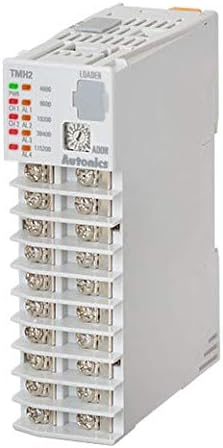
Figura 1: Frente view of the Autonics TMH2-42CE modular temperature controller. This image displays the terminal block connections for inputs and outputs, status indicator LEDs for power and channel alarms, and the 'LOADER' port for configuration. The model number 'TMH2' is visible on the top left of the unit's faceplate.
3. Configuração e instalação
Follow these steps for proper installation and wiring of the TMH2-42CE controller.
3.1 Montagem
The TMH2-42CE is designed for DIN rail mounting. Securely attach the unit to a standard DIN rail within an appropriate enclosure, ensuring adequate ventilation and clearance for wiring.
3.2 fios
All wiring should be performed by qualified personnel with the power disconnected. Refer to the terminal labels on the unit for correct connections.
- Fonte de energia: Connect a 24VDC power source to the designated power terminals. Observe polarity.
- Entrada CT: Connect the Current Transformer (CT) to the CT input terminals for current measurement.
- Digital Inputs (DI-1/2): Connect external switches or control signals to the DI-1 and DI-2 terminals as required for your application.
- Alarm Outputs (AL1-AL4): Connect external alarm devices or indicators to the respective alarm output terminals. These are typically relay outputs.
- Comunicação RS485: Connect the RS485 communication lines (A and B) to your master device for data exchange and remote control.
- Saída de controle: Connect your heating/cooling element or SSR to the selectable Current or SSR Drive Output terminals. Ensure the output type is configured correctly in the controller settings.
4. Instruções de operação
Once installed and wired, the TMH2-42CE can be configured and operated.
4.1 Ligar e configuração inicial
- Apply 24VDC power to the controller. The power indicator LED should illuminate.
- Access the controller's parameters via the 'LOADER' port using compatible Autonics software or a dedicated programming device.
- Configure basic settings such as input type (CT), output type (Current/SSR), and communication parameters (RS485 address, baud rate).
4.2 Setting Control Parameters
For each of the 2 channels, set the desired temperature setpoints, alarm thresholds, and PID control parameters (if applicable) according to your process requirements. Refer to the detailed programming guide available from Autonics for specific parameter codes and ranges.
4.3 Monitoramento e Controle
Monitor the current temperature readings and output status via the connected communication interface (RS485). The front panel LEDs provide visual indication of channel status and alarm conditions.
5. Manutenção
Regular maintenance ensures the longevity and reliable operation of your temperature controller.
5.1 Limpeza
Periodically clean the exterior of the unit with a soft, dry cloth. Do not use abrasive cleaners or solvents. Ensure no dust or debris accumulates in the ventilation slots.
5.2 Inspeção
Regularly inspect wiring connections for tightness and signs of damage. Check for any unusual odors, sounds, or visual anomalies during operation. Ensure the operating environment remains within specified temperature and humidity ranges.
6. Solução De Problemas
Esta seção fornece soluções para problemas comuns que você pode encontrar.
6.1 Problemas e soluções comuns
- Sem energia: Check the 24VDC power supply connection and ensure it is active. Verify polarity.
- Leituras incorretas: Verify the CT input wiring is correct and the sensor type is properly configured in the controller.
- No Output Control: Check output wiring. Ensure the control output type (Current/SSR) is correctly selected and the setpoint is appropriate. Verify alarm conditions are not preventing output.
- Communication Errors (RS485): Check RS485 wiring (A/B lines), communication parameters (baud rate, parity, stop bits, device ID), and termination resistors if applicable.
- Alarm LEDs Active: Review alarm settings and current process values to determine the cause of the alarm.
If problems persist, consult the detailed Autonics troubleshooting guide or contact technical support.
7. Especificações
| Recurso | Especificação |
|---|---|
| Modelo | TMH2-42CE |
| Marca | AUTONICS |
| Canais | 2 |
| Tipo de entrada | Entrada CT |
| Entradas Digitais | DI-1/2 |
| Saídas de Alarme | 4 (AL1, AL2, AL3, AL4) |
| Comunicação | RS485 |
| Fonte de energia | 24 VCC |
| Saída de controle | Selectable Current or SSR Drive Output |
| Fabricante | Autônicos |
| UPC | 645759343475 |
8. Garantia e Suporte
Autonics products are manufactured under strict quality control. This product is covered by a standard manufacturer's warranty against defects in materials and workmanship. For specific warranty terms and conditions, please refer to the official Autonics webou entre em contato com seu distribuidor local.
8.1 Suporte Técnico
For technical assistance, detailed product documentation, or service inquiries, please visit the official Autonics website or contact their customer support department. Provide your product model number (TMH2-42CE) when seeking support.
Autonics Official Website: www.autonics.com


