1. Introdução
The Hantek DSO2D50 is a high-performance digital storage oscilloscope designed for precise signal analysis and measurement. It features a 500MHz bandwidth, 2GSa/s real-time sampling rate, and an 80K memory depth. This instrument also integrates a 25MHz arbitrary waveform generator, making it a versatile tool for various electronic testing and development applications.
This manual provides essential information for the safe and effective operation of your DSO2D50 oscilloscope. Please read it thoroughly before use and retain it for future reference.
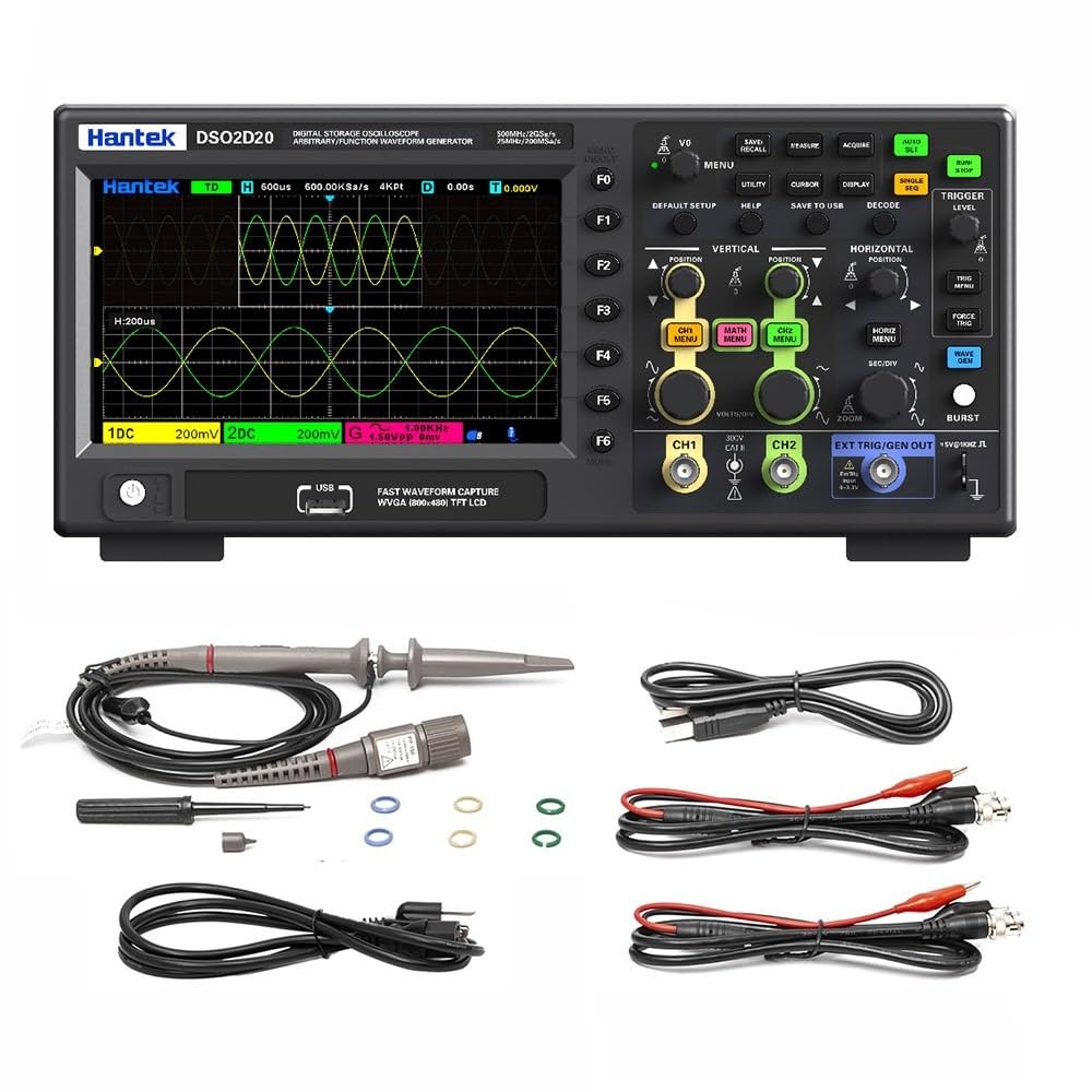
Figura 1.1: Frente view of the Hantek DSO2D50 Digital Storage Oscilloscope.
Principais características:
- 2 Analog Channels + 1 External Trigger Channel
- Largura de banda de 500 MHz
- 2 GSa/s Real-time SampTaxa de ling
- 80K Memory Depth
- Built-in 25MHz Arbitrary Waveform Generator
- 32 Automatic Measurement Functions
- 9 Triggering Modes
- Supports 1MΩ/50Ω Impedance Switching
- Multiple Data Storage Options (CSV, images, waveforms)
- Tela LCD de 7 polegadas
2. Informações de segurança
AVISO:
- To prevent electric shock, do not open the instrument casing. Encaminhe todos os serviços de manutenção para pessoal qualificado.
- Do not operate the oscilloscope in wet or damp condições.
- Certifique-se de que a fonte de alimentação voltage corresponde aos requisitos do instrumento.
- Utilize apenas o cabo de alimentação e os acessórios especificados pelo fabricante.
- Before making any connections, ensure the instrument is powered off.
- Always connect the ground lead of the probe to the circuit ground before connecting the probe tip to the test point.
- Observe all terminal ratings to prevent fire or electric shock.

Figure 2.1: Rear panel showing power input and safety warning.
Vol perigosotage inside, do not remove the cover unless by specified personnel.
3. Conteúdo da embalagem
Verifique se seu pacote contém os seguintes itens:
- 1 x Hantek DSO2D50 Bench Digital Storage Oscilloscope
- 2 x Passive Probes (typically 1:1/10:1 switchable)
- 1 x Cabo de alimentação
- 1 x Cabo USB
- 1 x Manual do Usuário (este documento)
- 1 x Calibration Certificate (may vary)
If any items are missing or damaged, please contact your dealer or Hantek customer support immediately.
4. Produto acabadoview
4.1 Controles e Conectores do Painel Frontal
The front panel of the DSO2D50 features the display, control buttons, knobs, and input connectors for channels and the arbitrary waveform generator output.

Figura 4.1: Detalhado view of the control panel and input connectors.
Key areas include:
- Área de exibição: 7-inch TFT LCD for waveform display and menu navigation.
- Botões de função (F0-F6): Context-sensitive buttons along the right side of the display.
- Botões do menu: Buttons like DEFAULT SETUP, UTILITY, CURSOR, DISPLAY, SAVE TO USB, DECODE, HELP.
- Controles verticais: VOLTS/DIV knobs and CH1 MENU, CH2 MENU, MATH MENU buttons for adjusting vertical scale and channel settings.
- Controles horizontais: SEC/DIV knob and HORIZ MENU, ZOOM buttons for adjusting horizontal scale and time base.
- Controles de gatilho: TRIGGER LEVEL knob and TRIG MENU, FORCE TRIG buttons for setting trigger conditions.
- Arbitrary Waveform Generator (AWG) Controls: WAVE GEN button and EXT TRIG/GEN OUT connector.
- Entradas do canal: Conectores BNC CH1 e CH2.
- External Trigger/AWG Output: EXT TRIG/GEN OUT BNC connector.
- Porta de host USB: Para conectar dispositivos de armazenamento USB.
4.2 Conectores do Painel Traseiro
The rear panel includes the power input and ventilation.
- Entrada de energia CA: Para conectar o cabo de alimentação.
- Ventilador: For cooling the instrument.
5. Configuração
5.1 Conexão de Energia
- Certifique-se de que a chave de alimentação do osciloscópio esteja na posição DESLIGADO.
- Conecte o cabo de alimentação fornecido à entrada de alimentação CA no painel traseiro do osciloscópio.
- Conecte a outra extremidade do cabo de alimentação a uma tomada elétrica CA aterrada.
5.2 Conexão e Compensação da Sonda
- Connect a passive probe to one of the CH1 or CH2 BNC input connectors.
- Set the probe attenuation switch (if applicable) to 10X.
- Connect the probe ground clip to the oscilloscope's ground terminal (usually a dedicated terminal or the ground ring of the BNC connector).
- Connect the probe tip to the probe compensation output (usually a square wave test signal output on the front panel).
- Ligue o osciloscópio.
- Pressione o AJUSTE AUTOMÁTICO button. The oscilloscope will automatically adjust settings to display the compensation signal.
- Ajuste o parafuso de compensação na sonda até que uma onda quadrada de topo plano seja exibida na tela. Isso garante medições precisas.
6. Instruções de operação
6.1 Basic Waveform Display
- Ligue o osciloscópio.
- Connect a compensated probe to CH1.
- Connect the probe tip to the signal source you wish to measure.
- Pressione o AJUSTE AUTOMÁTICO botão. O osciloscópio ajustará automaticamente as configurações vertical, horizontal e de disparo para exibir uma forma de onda estável.
- Use o VOLTS / DIV knob to adjust the vertical scale (ampsolidão).
- Use o SEG/DIV knob to adjust the horizontal scale (time base).
- Use o POSIÇÃO Botões para mover a forma de onda verticalmente ou horizontalmente.
6.2 1MΩ/50Ω Impedance Switching
The DSO2D50 supports switching between 1MΩ (high impedance) and 50Ω (low impedance) input impedance. This is crucial for adapting to different measurement scenarios and ensuring signal integrity, especially for high-frequency signals or when matching transmission lines.

Figure 6.1: Menu for selecting input impedance.
To switch impedance:
- Pressione o CH1 MENU or CH2 MENU button for the desired channel.
- Navigate through the menu options using the function buttons (F0-F6) until you find the "Impedance" setting.
- Selecione qualquer um 1 MOhms or 50Ω as required for your measurement.
- Observação: When using 50Ω impedance, ensure your signal source is also 50Ω terminated to prevent reflections.
6.3 Measurement and Statistical Functions
The oscilloscope provides 32 automatic measurement functions and threshold measurement functions. These tools support statistical analysis, allowing you to display five measurement values: current value, average value, maximum value, minimum value, and standard deviation.

Figura 6.2: Example of automatic measurement display.
To access measurement functions:
- Pressione o MEDIR botão.
- Use the function buttons to select the desired measurement type (e.g., Frequency, Period, Vpp, Vmax, Vmin, Rise Time, Fall Time).
- The selected measurements will appear on the screen.
- Para view statistical values, navigate to the statistical menu within the MEASURE options.
6.4 Built-in Arbitrary Waveform Generator (AWG)
The DSO2D50 includes a 25MHz arbitrary waveform generator capable of outputting five standard waveforms: sine wave, square wave, triangle wave, exponential wave, noise, and DC. It also supports custom arbitrary waveform output.

Figure 6.3: Arbitrary Waveform Generator settings interface.
To use the AWG:
- Conecte um cabo BNC da EXT TRIG/GEN OUT connector to the input of the device under test or an oscilloscope channel.
- Pressione o WAVE GEN botão.
- Use the function buttons to select the desired waveform type (Sine, Square, Triangle, etc.).
- Adjust parameters such as Frequency, Amplitude, and Offset using the corresponding menu options and knobs.
- Ensure the AWG output is enabled within the menu.
6.5 Triggering Modes
The oscilloscope offers 9 triggering modes to stabilize and capture specific events in your waveform. Common modes include Edge, Pulse, Video, Slope, and more advanced options for serial bus decoding.
To set up a trigger:
- Pressione o TRIG MENU botão.
- Select the desired trigger type (e.g., Edge, Pulse).
- Adjust the trigger source (CH1, CH2, EXT), slope (rising/falling edge), and level using the TRIGGER LEVEL knob and menu options.
- The trigger level is indicated by a horizontal line on the display.
6.6 Armazenamento e Recuperação de Dados
The DSO2D50 allows you to save and recall various data types, including CSV files, images, reference waveforms, and waveform data, to a USB storage device.
To save data:
- Insert a USB flash drive into the USB Host port on the front panel.
- Pressione o SAVE TO USB botão.
- Select the desired save type (e.g., Image, Waveform, CSV) and file format from the menu.
- Confirme a operação de salvamento.
6.7 Funções Avançadas
- Funções matemáticas: Perform waveform arithmetic operations (e.g., A+B, A-B, A*B, A/B, FFT) and support cursor measurements for detailed analysis.
- FFT Scale Display: Provides a clear display for frequency domain analysis, making it easier to read results.
- Modo XY: Use XY mode to analyze the phase relationship between two signals. This is useful for Lissajous figures.
- Serial Protocol Triggering and Decoding: Supports protocols such as UART, LIN, CAN, SPI, and IIC, enabling easy analysis of serial bus data.
- SCPI Remote Control: Standard SCPI commands are supported for easy system setup and remote control via USB.
7. Manutenção
7.1 Limpeza
- Clean the instrument's exterior with a soft cloth dampvido com detergente suave e água.
- Do not use abrasive cleaners or solvents that may damage the casing ou exibição.
- Ensure no liquid enters the instrument.
7.2 Armazenamento
- When not in use for extended periods, store the oscilloscope in a dry, dust-free environment.
- Evite temperaturas e umidade extremas.
- Disconnect all probes and the power cord before storage.
7.3 Calibração
The DSO2D50 is factory calibrated. For continued accuracy, periodic calibration by qualified service personnel is recommended, typically every 1-2 years depending on usage.
8. Solução De Problemas
| Problema | Possível causa | Solução |
|---|---|---|
| Sem exibição após ligar. | Power cord not connected, power switch off, or power supply issue. | Check power cord connection. Ensure power switch is ON. Verify power outlet functionality. |
| Nenhuma forma de onda exibida. | Probe not connected, signal source off, vertical/horizontal scale incorrect, or trigger not set. | Check probe connection. Ensure signal source is active. Press AJUSTE AUTOMÁTICO. Adjust VOLTS/DIV and SEC/DIV. Check trigger settings. |
| Forma de onda instável. | Configurações de gatilho incorretas. | Adjust trigger level. Change trigger type (e.g., from Auto to Normal). Check trigger source. |
| As medições são imprecisas. | Probe compensation incorrect, probe attenuation setting mismatch, or incorrect impedance. | Perform probe compensation. Ensure probe attenuation (1X/10X) matches oscilloscope setting. Verify input impedance (1MΩ/50Ω). |
| USB storage not recognized. | Incompatible USB drive, drive not formatted correctly, or drive issue. | Try a different USB drive. Ensure drive is formatted to FAT32. |
9. Especificações
The following table outlines the key specifications for the Hantek DSO2D50 Digital Storage Oscilloscope.
| Parâmetro | Especificação |
|---|---|
| Modelo | DSO2D50 |
| Canais | 2 Analog Channels + 1 External Trigger Channel |
| Largura de banda | 500 MHz |
| SampTaxa de ling | 2 GSa/s (Real-time) |
| Profundidade de memória | 80 Kpts |
| Gerador de forma de onda arbitrária | 25 MHz (Sine, Square, Triangle, Exponential, Noise, DC) |
| Sensibilidade Vertical | 500 µV/div - 10 V/div |
| Impedância de entrada | 1 MΩ ±2% || 15 pF ±5 pF; 50 Ω ±2% |
| Vol. Máx. De Entradatage | 300 V CAT II (1MΩ) |
| Mostrar | LCD TFT de 7 polegadas |
| Modos de gatilho | Edge, Pulse, Video, Slope, Overtime, Window, Pattern, Interval, UART, LIN, CAN, SPI, IIC |
| Medições automáticas | 32 types, with statistical analysis |
| Interface | USB Host, USB Device |
| Fonte de energia | 100-240 V CA, 50/60 Hz |
| Consumo de energia | < 50W |
| Dimensões | (Refer to package dimensions, typically 5.91 x 3.94 x 0.79 inches for package, actual unit size will be larger) |
| Peso | 12.1 libras (peso do item) |
Observação: Specifications are subject to change without notice. For the most current specifications, please refer to the manufacturer's official website.
9.1 Comparação de modelos
The Hantek DSO2D50 is part of a series of oscilloscopes. The following table provides a comparison with other models in the series, highlighting key differences.

Figure 9.1: Model comparison table for Hantek oscilloscopes.
This table helps to understand the DSO2D50's position within the product line, specifically noting its 500MHz bandwidth, 2GSa/s sampling rate, 80K storage depth, and integrated arbitrary function generator (AFG).
10. Garantia e Suporte
10.1 Informações de garantia
Hantek products are typically covered by a limited warranty against defects in materials and workmanship. The specific warranty period and terms may vary by region and product. Please refer to the warranty card included with your product or visit the official Hantek website para obter informações detalhadas sobre a garantia.
Guarde o recibo de compra como comprovante para solicitações de garantia.
10.2 Suporte ao cliente
For technical assistance, troubleshooting, or service inquiries, please contact Hantek customer support:
- Fabricante: Qingdao Hantek Electronic Co., Ltd
- Endereço: #35 Building, No. 780 Baoyuan Road, High-tech Zone, Qingdao, Shandong, China 266114
- Website: (Please refer to the official Hantek website for contact forms or email addresses)
When contacting support, please have your product model (DSO2D50) and serial number ready.


